Using the L293D H-Bridge Motor Driver with Arduino
By Aditya
/
September 29, 2019
In this blog, I will be explaining how to use the popular L293D motor driver IC (often misspelled as L239D) along with an Arduino to control the direction and speed of DC motors. I shall also be explaining H-Bridge circuits, which motor drivers like the L293D are based on, which can be very helpful in many electronics and robotics projects. Let's get started!
Role of H-Bridges in driving motors
A DC motor (Direct Current motor) is a motor which rotates when a voltage is applied across its terminals. The speed of the motor is proportional to the voltage while direction is dependent on the sign of the voltage (direction of flow of current current).
Simply put, a DC motor rotates when you connected to a DC power source (like a battery). The greater the voltage, the faster it will spin. If the power source is connected in reverse, the motor will spin in the opposite direction, but with the same speed as before. This is exactly how the speed and direction of a DC motor are controlled.
While the speed control can be done fairly easily by a microcontroller (using Pulse Width Modulation), DC motors usually require more current than most microcontrollers can provide directly from their pins. This is where H-Bridges com in. H-Bridges are circuits which allow bi-directional current amplification, allowing the microcontroller to drive the motor in both directions without providing the power to do so directly (and getting damaged). Some H-Bridges (Like the L293D) also provide enable pins to allow speed control. When the enable pin is held low, the IC stops driving the motors. Providing a PWM signal on this pin allows the speed of the motor to be controlled. You can visualize that the H-Bridge operates between the Microcontroller and the Motor, as shown below.
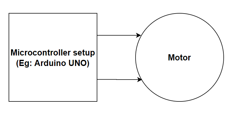
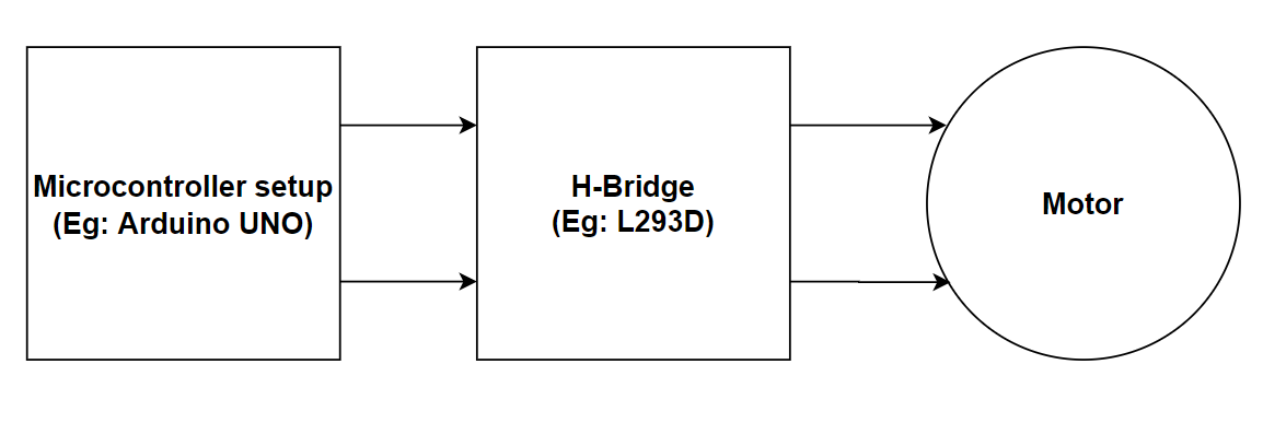
The H-Bridge supplies power to the motor using an independent power source. However, it is the microcontroller which (through a small current) controls the H-Bridge i.e. the direction and speed of the motor.
Working of an H-Bridge circuit
The H-Bridge gets its name from its "H" shaped configuration. Shown below is a schematic describing it.
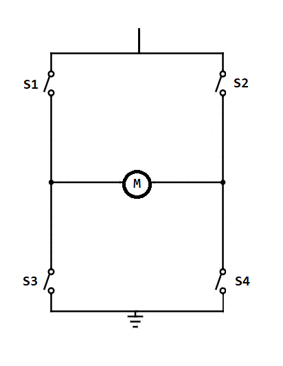
It contains four switches (S1-S4) and is connected to a load (motor - M) that should be driven. Alternating pairs of switches can be switched on and off to control the direction of current through the load. This is how the H-Bridge is used to achieve bi-directional motor control. Shown below are the configurations required to provide current flow in either direction.
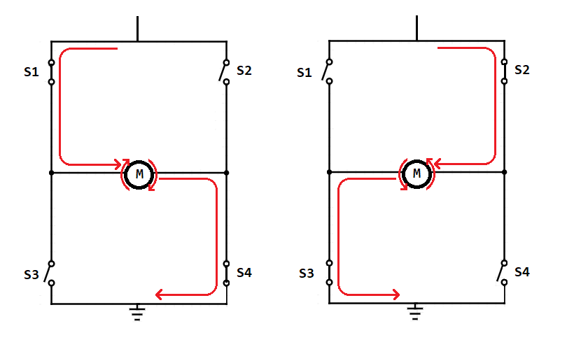
In the above diagrams, I have used physical switches, but these can be replaced with transistors. A transistor acts like a switch (capable of connecting or disconnecting its two junctions), but unlike a regular switch that can be physically manipulated, a transistor depends on an external current to connect/disconnect their junctions. This allows an external component, such as a microcontroller to control the H-Bridge and drive the motors.
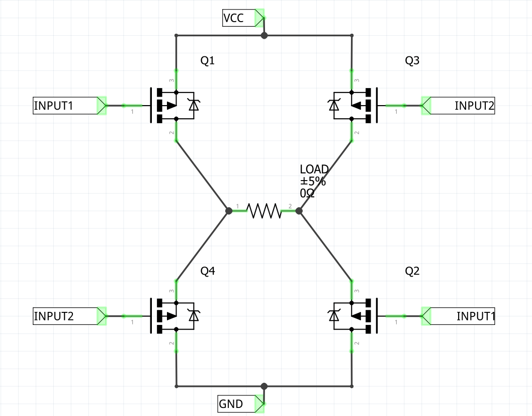
Alternating pairs of transistors are connected together, just like the switches used before, which brings down the pins used to control the motors to two. The current needed to control the transistors is very weak compared to the current that can flow through them and drive the load.
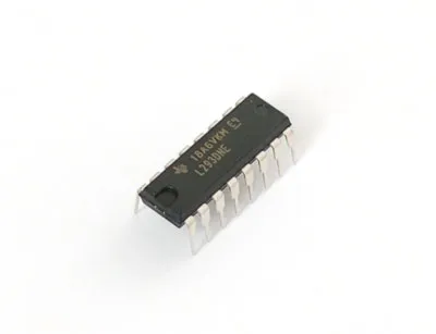
While it is possible to construct your own H Bridge using individual transistors, in this blog we will be using the L293D (often mis-spelt as L239D) as it is compact, popular and comes in many different breakouts (as well as the IC alone).
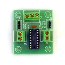
Shown below is the L293D IC in standalone and breakout forms.
Configuration and working of the L293D IC
The L293D is a very popular H Bridge IC. Internally, it contains two H Bridges allowing you to individually drive 2 motors bidirectionally up to 36V at 0.6A each (1A for short spurts). This amounts to 21.6 Watts (36 Watts for short Spurts). It also contains two enable pins, one for each side.
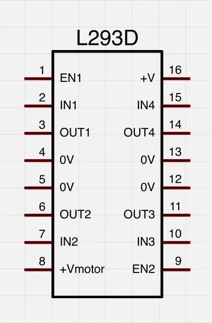
Power & Grounding: Pins 16 (VSS) and 8 (VS) need to be connected to the positive terminal of your power supply which will be used to drive the load. Pins 4, 5, 12 or 13 (all are GND) need to be connected to the negative terminal. Optionally, they can also be used to solder a heat sink onto the chip. The four ground pins are connected to each other and connecting even one of them is enough, however it is recommended to connect wires to all of them to manage heating issues better.
Controlling the Direction: Pins 2 and 7 (INPUT 1 and 2) are used for controlling the states of pins 3 and 6 (OUTPUT 1 and 2) which get connected to the load such as a motor. The state of each input pin reflects the state of its respective output pin. For example, setting the state of pin 2 (INPUT 1) and 7 (INPUT 2) to high and low respectively will cause pins 3 (OUTPUT 1) and 6 (OUTPUT 2) to be set to high and low respectively and vice-versa. In other words, current can flow in either direction by reversing the states of the INPUT pins. These pins are the alternating switches of the H-Bridge.
Similarly, pins 10 and 15 (INPUT 3 and 4) are used for controlling pins 11 and 14 (OUTPUT 3 and 4), allowing a second load to be connected and driven independent of the first.
Controlling the Speed: There exist to special pins on the L293D called the enable pins - Pins 1 and 9 (ENABLE 1 and 2). Setting an enable pin to high, switches on or "enables" its respective H Bridge circuit while setting it low, breaks the circuit.
They can be provided with a PWM signal with varying duty cycles to control the speed of the motors. If you are not familiar with how PWM works, click here for my tutorial on the same.
Circuit for Arduino, L293D and motors
In this section, I will be showing how to assemble a test circuit to drive a single motor using an Arduino UNO and the L293D. Here is a list of the components you will require -
- An Arduino UNO (any alternate Arduino or equivalent microcontroller will work)
- A DC motor
- The L293D H-Bridge
- A breadboard
- A suitable power supply to drive your motor (I have used a 9v battery)
If you are not familiar with Arduino, then you can click here to go to my tutorial on getting started with Arduino.
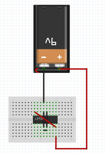
First connect the pins of your power supply to the L293D. This includes the positive and negative pins. The positive supply goes to the VSS and VS while the negative goes to GND as shown-
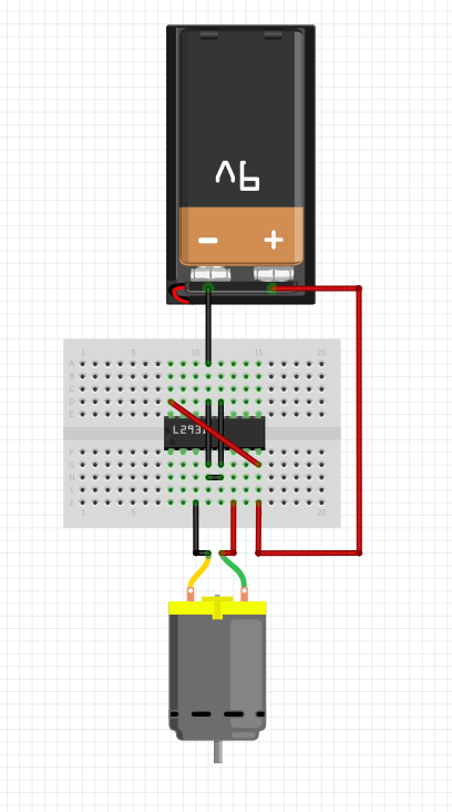
Next, connect the motor to the output pins of the IC as shown -
Finally, connect two digital pins of the Arduino to the input pins of the IC (on the same side as the motor) and a third pin (PWM capable) to the enable pin of the IC for speed control. The PWM capable pins are marked with a tilda symbol (~) before them. I have used pins 7, 8 and 9.
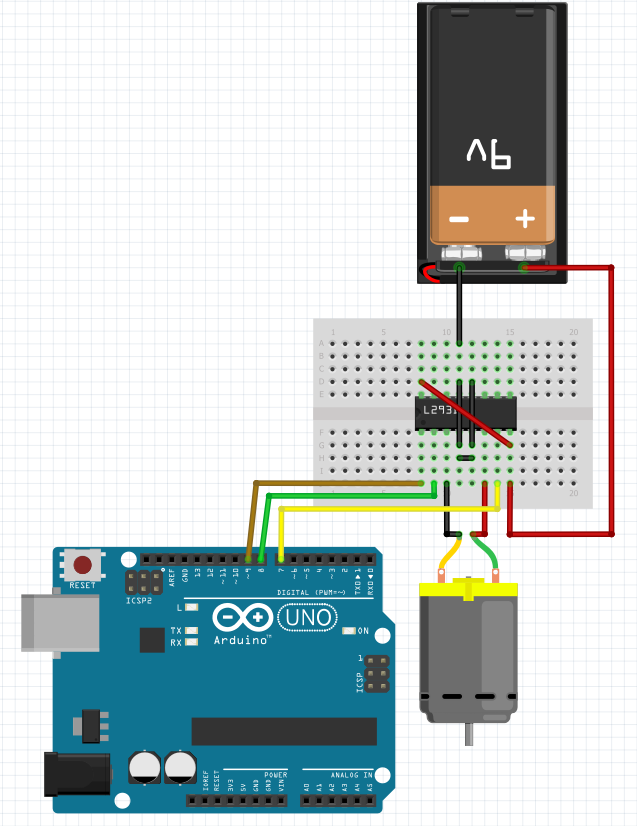
The red and black wires coming out of the battery indicate positive and negative polarity respectively. The red and black wires going to the motor represent the polarity to turn the motor in the clockwise direction (i.e. to spin the motor in the clockwise direction, current must flow from the red wire to the motor and out of the black wire). The green and yellow wires are the direction control wires while the brown wire is for speed control.
This completes the circuit.
Program to drive motors via L293D
In this section I will be showing and explaining the code to drive the circuit asembled above. It will accelerate the motor from stationary to maximum speed, de-accelerate it and repeat this in the opposite direction, with this whole cycle repeating indefinitely. This uses the complete functionality of the motor driver.
Start by defining the pins you will be using to drive the motors. In the above circuit I have used pins 7, 8 and 9 and will be defining them as IN1, IN2 and EN. Next, set each of their pin-modes to output in the setup.
Next, create functions which will be used to change the speed and direction of the motors. The speed control function takes an integer value between 0 and 255 its parameter and sets EN to the given value. The direction control function takes a boolean value (either High or Low) as its parameter and sets one IN1 to the given value and IN2 to the inverse of this value (High becomes Low and Low becomes High).
Finally, in the main loop, create four for loops, two going from 0 to 255 and two from 255 to 0, alternating between the two. Before each pair of for loops, set the direction of the motor. In each iteration of the loop, change the speed of the motor to match the state of the loop. Also add a small delay (I have used 15 milliseconds) in each loop to make sure you can see the changes.
The complete code should look a bit lik this-
Now, you can compile and upload your program and if everything was done right, the motor should start spinning! That's it, you're done!
Final Remarks
As I have said, L293D has the capability to control not just one but two motors. You may try to control two motors with the Arduino simultaneously, with both of them spinning at different speeds, in different directions.
If you found this blog helpful, leave a comment down below. I would love to know your thoughts!