Using PWM (Pulse Width Modulation) to control LED brightness with Arduino
By Aditya
/
April 9, 2019
In this tutorial, I will explain the theory Pulse Width Modulation (PWM), and how to use it with an Arduino to control the brightness of an LED. Generally, any digital device like an Arduino deals only with two states i.e. ON(5v) or OFF(0v). However, in many situations we desire to have analog states which are somewhere in between these two.
An ON state could be a motor going at full speed or an LED at its maximum brightness. Analogously, an OFF state would be the same motor stationary, or the LED that is not emitting any light. Using PWM, we use these two states to produce an apparent voltage between these two states. Do not get intimidated by the terminology, the technique is in fact very simple an elegant (and implemented in the Arduino in a very easy-to-use way. Let's get started!
How does PWM work?
PWM, which stands for Pulse Width Modulation, is a technique used to convert digital voltages to apparent analog voltages. A microcontroller is a digital device that can normally output either 0v or 5v (some microcontrollers may use 3.3v). Consequently, any devices they power can either be switched off or on, even if intermediate states are needed. Considering the LED, we might be required to control its brightness, rather than simply switch it off or on.
Using PWM, a pin is selected and its voltage is switched between 5v & 0v extremely fast, with the pin staying on each voltage for a variable amount of time. This gives the effect of a voltage between 5 and 0 being present. Do keep in mind that this needs to be done at an extremely fast rate, otherwise the desired effect will not be produced. In this example below, a voltage of 2.5v needs to be generated using 5v and 0v. Here is how the state of the pin will look after graphing it-
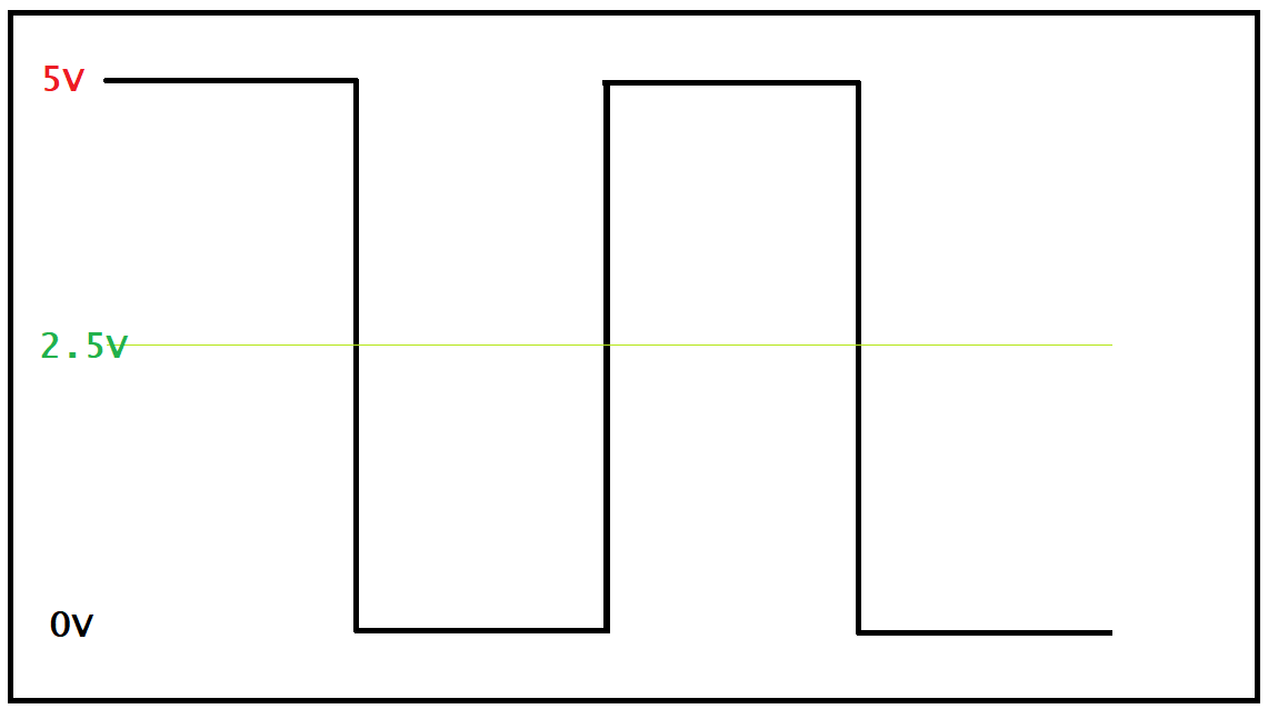
The pin is switched between 5v and 0v, staying on each for equal amounts of time. This ratio of 1:1 gives the effect of the output being 2.5v. Once again, the amount of time the pin stays on each state is extremely low (in the order of microseconds or even lesser).
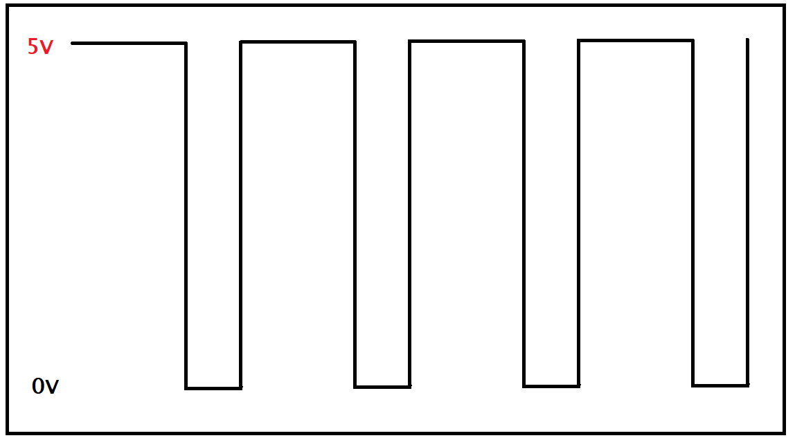
In this graph, the pin is set to 5v for twice as long as it is set to 0, i.e the ratio becomes 2:1. This gives the illusion of 3.3v being present.
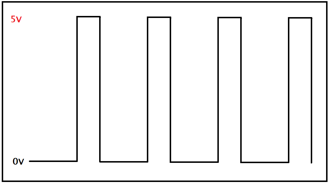
Here is another example, but this time the voltage is set to 0v for twice as long as 5v, which is in the ratio 1:2. This gives the illusion of the voltage being 1.67v.
Now that we have some understanding of the working of PWM, let us see how we can use it to control the brightness of an LED with an Arduino.
Step 1: Gathering the parts
In this step I will be listing all the necessary parts you require and how you can get them.
- Arduino (or equivalent microcontroller)
Arduino UNO - USB Cable (to program the Arduino)
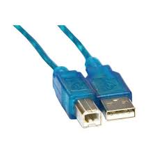
USB Cable - 5/3mm LED
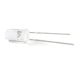
3/5mm LED
These parts can be bought from any online vendor as for your convenience I have listed some places at the end of this tutorial. You might even have these parts already if you have read and tried the example from my blog on getting started with Arduino.
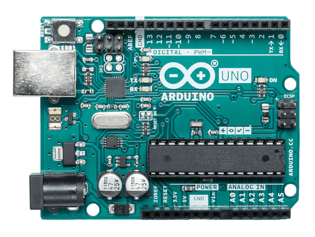
Step 2a: Understanding the different pins on an Arduino
Before we start building the circuit, it is useful to understand the different types of pins on the Arduino and which of them support PWM natively. Though other pins can be made to perform PWM but this would require the programmer to manually code it and use techniques like interrupt programming. As for the pins which support it natively, it can be done with simple direct calls to some functions as we will see ahead. Let us understand the pins first. They can be divided into the following types-
- Power pins
- Analog input pins
- Digital IO pins (some of which are PWM capable, and are marked with the
~symbol)
The Power pins are pretty self-explanatory, i.e. they are used for providing power to the circuit. For example, the Vin, VCC, GND pins are all power pins.
The Analogue Input pins are those pins which can be used for either reading analogue signals or outputting digital signals. They cannot, however, be used for performing PWM to generate analogue signals. They are the pins which have an "A" before their pins number. For example, on the UNO pins A0 to A5 are analogue input pins.
The Digital IO pins are those pins which can be used for digital input as well as output. These are the pins which are numbered ordinarily without any special characters. For example, on the UNO, pins 0 to 13 are digital IO pins. They are capable of outputting digital signals and reading digital signals.
Few special digital IO pins, marked with a tilda (~) character before them are capable of PWM natively, meaning they do not require manual programming. The whole work of switching on and off at required frequency is handled internally. Here is a list of the pins which support PWM on various Arduinos.
Step 2b: Setting up a simple PWM circuit
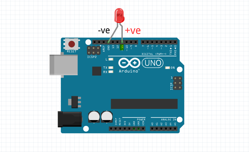
In this step, I will be showing how to build the circuit for this project. Start by connecting the shorter -ve leg(called cathode) of the LED to any GND pin on the Arduino and the longer +ve leg(called anode) to any PWM-capable pin. In the below image I have connected it to pin 11 because it is close to a GND pin and this allows me to skip using breadboards and extra wires.
Step 3: Code for LED brightness control
In this step, I will explain code required to use the above circuit for changing the LED's brightness. If you are not familiar with how to use the Arduino IDE, please see my blog on getting started blog. Shown below is a short program to demonstrate this.
Now, let us understand the code step by step.
In this segment, I create a variable called pwm and give it a value of 11. Replace 11 with whichever pin you have used. I then set the pin to output mode.
Now, let us understand the code step by step.
Next, I send an analogue value(0 to 255) to the pin using the analogWrite function. The function accepts all whole number values from 0 to 255. Any value higher or lower will result in an error. Any decimal values are also not allowed. The value passed represents a voltage between 0 and 5v.
The conversion formula is-
value = (required_voltage)*255/5
This can be further simplified to-
value = (required_voltage)*51
Using this, you can see that the program first sets the voltage to 5v and waits for 750 milliseconds. It then sets it to 2.5v and waits once more. It finally sets it to 0v and waits one last time. This is repeated indefinitely.
The setting of 2.5v i.e. analogWrite(pwm,127) is internally doing the cycles of On and Off at the required frequency to produce this output via the PWM capable pin. We don't have to do this in our code. This is how PWM is natively supported on Arduino.
You can compile and upload the code to the board now, and if everything has gone well you should see the LED switch on, change to half the previous brightness (but still stay on) and finally switch off.
Step 4: Playing around a bit
Now that we have understood the program, let us tweak it and play around a bit.
Try replacing analogWrite(pwm, 255) with digitalWrite(pwm, HIGH). You will see that this does not change the output. This is because in both cases, you are telling the pin to do the same thing, which is be on 100% of the time, giving an output of 5v. The same can be said for analogWrite(pwm, 0) and digitalWrite(pwm, LOW), as both tell the pin to be off 100% of the time, that is output 0v. The type of pin does not matter when we are dealing with On or Off state as that is the normal behavior expected of a microcontroller.
You can try replacing the values to see how the brightness of the LED changes. You may even write a program that gradually fades the LED from being off to on and back.
All comments are welcome below!