Getting started with Arduino
By Aditya
/
March 2, 2019
In this tutorial, we will see a guide on how to get started with the popular and flexible Arduino platform by blinking an LED using the Arduino UNO Board. We will first get the required parts, build and understand the circuit and write a complete program to control the circuit and upload it to the Arduino. Let's get started!
This guide requires some basic knowledge of programming, and knowing a little bit of C++ will help for sure.
Getting the required parts
Before we can get started with blinking an LED with the Arduino UNO, let us see the parts required.
- Arduino/Genuino UNO (along with USB cable for programming)
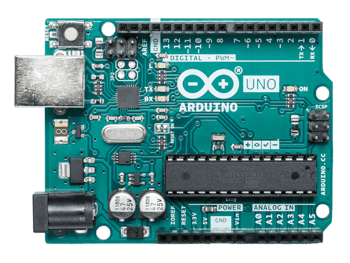
Official Arduino UNO R3 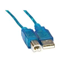
USB Cable This is the microcontroller, i.e. the brains of the project. The Arduino has pins, that are used to control external components such as sensors, motors, etc. The pins (and Arduino) are controlled by the program that we will write. If you do not have an official Arduino/Genuino UNO, a clone will work as well.
- 5/3mm LED
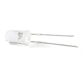
5mm LED Make sure to use either a 5 or 3 mm LED (a larger one might draw too much current and consequently damage the Arduino). We will connect the LED to one of the pins on an Arduino UNO and write a program to blink it.
- 270 Ohm Resistor
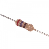
270 Ohm Resistor A resistor is required along with the LED to limit the current it can draw. The resistance of an LED is non-constant and decreases as the voltage across it increases. This can cause it to quickly start drawing too much current, which can end up damaging both itself and the Arduino's pins. Therefore, we need an external resistance which can limit the current to a safe amount that is high enough to light the LED but low enough to not damage/stress any of the components.
While the perfect resistance depends on factors such as the size and color of the LED (blueish colors require higher resistances and redder colors require lower resistances), a value of 270 Ohms is good enough to use regardless. We can now use Ohm's law to calculate the maximum current that can flow through the circuit, which comes out to 18 milliamps. This is enough to light the LED, yet still lower than the 20 milliamps given in the Arduino UNO's documentation.
- Breadboard & Wires
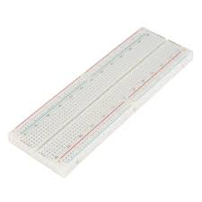
Breadboard 
Connecting Wires This is the microcontroller, i.e. the brains of the project. The Arduino has pins, that are used to control external components such as sensors, motors, etc. The pins (and Arduino) are controlled by the program that we will write. If you do not have an official Arduino/Genuino UNO, a clone will work as well.
The breadboard makes it easy to connect the LED, resistor and Arduino UNO together.
After collecting all the parts, we can now move on to building the circuit.
Building the Circuit
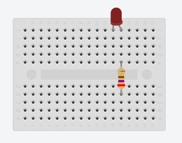
In this step, we will connect all the parts together and build the circuit for blinking the LED. The first step is to connect the LED and the resistor together on the breadboard, as shown. While you can connect the resistor to any side of the LED, it is a good practice to connect it to the positive (anode) side.
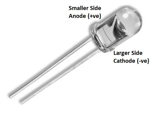
The longer leg of the LED is the positive (anode) side while the shorter leg is the negative (cathode) side. If the legs have been cut to the same length or you are still unsure, then you may use the following image as a reference.
After connecting the LED and resistor, connect the Arduino to it as shown below. The resistor should be connected to pin 13 while the LED's cathode to any of the available GND pins.
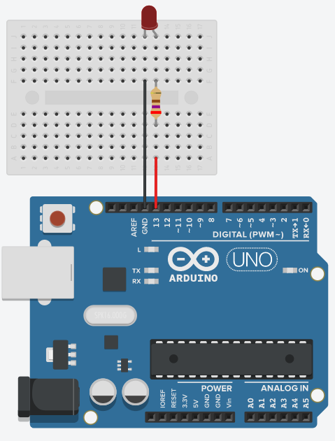
This should complete the circuit. To switch the LED on, we will have to provide the flow of current in the following direction, similar to when we directly use a battery/DC power source. This current will be provided by the Arduino's pin (pin 13), travel through the LED and finally reach the GND pin, where the circuit gets completed.

After connecting the circuit we can move on to setting up the IDE.
Setting up and understanding the IDE
Arduino is a complete platform, i.e. it gives you the software (IDE), the hardware (Boards), and a place to discuss doubts and ideas (the forums and project hub). In this step, we will install and set up the software required to program Arduino boards.
The first tool we will need is the Arduino IDE. An IDE (Integrated Development Environment) is a single tool which combines various tools used while programming into a single interface and automates their usage. As its name suggests, the Arduino IDE is a complete program which allows you to write Arduino programs, verify them and upload them from the same interface. It makes the whole programming process quick and easy, so that you can focus on what you are building rather than the tools.
As an alternative to the Arduino IDE, there is also a web editor which runs on your browser and serves the same functionality, that you can use without having to set up any software. The downside to this is that you are only allowed to write a limited number of programs a day.
You can start by going to the Downloads Page on the Official Arduino Website and scrolling to the Download Options as shown below.
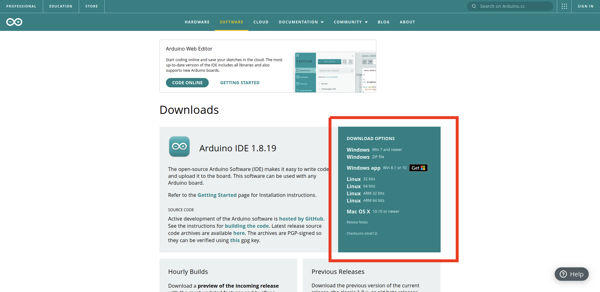
This includes the installers for the latest versions of the IDE for all platforms. Click on the option appropriate for your platform.
If on Windows, you could either download the installer (first option), a zip file containing the IDE (second option) or you could even install it as an App from the Microsoft Store. It is recommended that you use the installer since it walks you through all the steps one by one and allows you to specify the installation directories, components to install, etc. The default values selected by the installer should work in most cases.
If on Linux instead, choose the option which corresponds to your Platform to install a tar file. The tar file should include a folder that contains two shell scripts for installing and removing the IDE respectively. Simply run the install.sh file using bash (or any other terminal) to start the process.
After completing the installation process, you start the IDE. Here is how it should look.
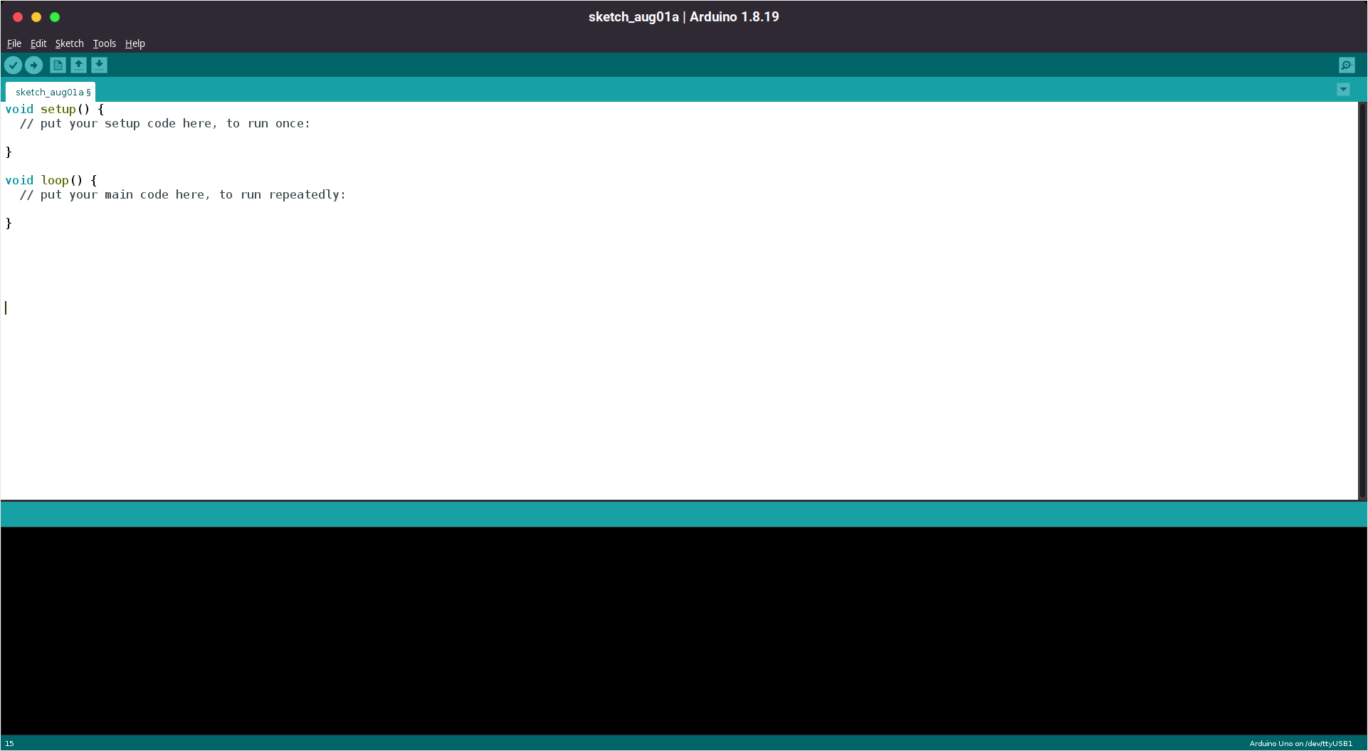
Let us go over its parts one by one. Below the menu bar (File Edit Sketch...), and starting from the left we have the following.
- The build/verify button (marked with a Tick Mark). It is used to build your program and verify if there are any errors. This converts your program from a human-readable for to something that can be uploaded to an Arduino. You can also invoke this using the keyboard shortcut Ctrl+r.
- The upload button (marked with a Right Arrow). Once the program has been built and an Arduino is connected to your PC, pressing this button will upload it to the board. After the upload process is complete, the board will start running your program. You can also invoke this using the keyboard shortcut Ctrl+u.
- The new button (marked with a single page). Clicking on this button will immediately open a new window with a blank program. You can also invoke this using the keyboard shortcut Ctrl+n.
- The open button (marked with an Up Arrow). It is used for opening a new program or a built-in example. Clicking on it should cause a dropdown to appear to select what program to open. You can also invoke this using the keyboard shortcut Ctrl+o.
- The save/save as button (marked with a Down Arrow). It is used to save the file you are currently working on. If the file has not been saved already, it should open a new window to ask for the name and location of the program. You can also invoke this using the keyboard shortcut Ctrl+s.
We will see what each of these actions means and does in the following sections. Do not worry if you do not completely understand what they mean for now.
The next line contains all the open tabs (files) which you are currently working on. One of the features of an IDE is that it can have multiple files open (and being edited) simultaneously. That being said, we will only work on a single file for now. The remaining screen area is taken by whatever file you are currently working on. We will see how to write code for the Arduino in the next section.
The green and black bars in the second half of the screen are for showing the status of the program and result of user actions respectively.. Actions such as saving, verifying, uploading, and the status of the verify/upload process (done or not) are displayed in the green bar.
You can see this in action by saving the current program and naming it blink_example. When completed, you should see the words Done Saving. appear in the green bar. The black bar shows verbose information about each of the steps, errors while verifying, etc.
For a more detailed explanation of the IDE and its features, click here. If you wish to use the web editor, click here. If you are having any trouble installing the IDE or using it, you can also try searching for it on the Arduino Forum.
After understanding the environment, we can move on to writing the code.
Writing the program
In this step, we will write a basic program to blink the LED that we connected to the Arduino. You can start by opening your IDE and saving the current program in a convenient location with a convenient name. If you have been following the previous step, you should already have a project named blink_tutorial ready.
On the Arduino platform, Individual code files are called sketches and are written in a slightly modified version of C++. If you go to the location where you saved the program, you will see a directory that contains the program (blink_tutorial.ino) rather than a single sketch. The file and directory should share the same name. This is done by the IDE because it needs to store a lot related files apart from the code files. These files are generated by the IDE automatically as and when needed and you do not have to worry about them for now. As mentioned before, we will only use a single file for now.
In the beginning, the IDE should auto-generate the following code. If it has not, please copy and paste it into your file.
All lines that begin with a // are comments/remarks. They play no part in the program's execution and are put by the programmer for explaining code/writing a message etc. Additionally, all statements must end with a semicolon (;). We will see what this means in a bit.
The lines void setup() and void loop() are used to declare functions. A function is a small collection of reusable code. A function is allowed to accept certain arguments and return some values. We specify the type of value returned by a function by prefixing their name with the type. For example, if they return an integer (a positive or negative number without the decimal point), then we specify int or if they return no value at all, then we specify void. In the above case, the functions are named setup and loop and they return no value. The parameters (and their types) that are accepted by the function are put in the brackets that follow their names. If no parameters are accepted, then we leave the brackets empty. In the above case, the functions setup and loop do not accept any parameters. The code to be executed by a function are put in the curly braces following its declaration. This is the function's definition.
setup and loop are functions provided to you by the Arduino Platform by default. Any code entered in the setup function is executed once when the Arduino is powered on and the code in the loop function is executed repeatedly after that.
To be able to blink the LED, we must first tell the Arduino to make pin 13 an output, i.e. we will control the current being output from it rather than read its state. To do so, enter the following code in the setup function.
The program is case-sensitive, i.e. output and OUTPUT are treated differently, so be careful. The pinMode function is a builtin Arduino function that accepts the pin number and mode of the pin that we want to update. We enter this code in the setup because we only want the pin's mode to be set once during startup. We add the semicolon at the end of this line since it consists of a statement that tells the Arduino to do something. The semicolon is not added after the curly braces or the function names, since they aren't statements to the program. You will get better at differentiating between the two with time.
The next step is to tell the Arduino to switch the LED on, i.e. set the digital state of the pin to HIGH. Enter the following code in the loop function.
The digitalWrite function is also a builtin Arduino function and it tells the Arduino to update the digital state of a pin (set it to a low 0v state or a high 5v state). We can similarly switch the LED off as follows.
This code should be enough to blink the LED, but it will be too fast for the human eye to observe, since the Arduino will execute it as fast as it can. To be able to see the LED blink, we have to add a delay after each state change. To do, we can use the delay function as shown below.
The delay function is a builtin Arduino function that halts the program execution for the provided number of milliseconds. Recall that a single second has 1000 milliseconds, and the above code code makes the LED blink once per second, which is enough to be viewable.
While the code is syntactically and logically correct, it still has one problem. The pin number we are using is hard-coded into the program, and if we change the pin the LED uses, then it needs to be manually changed everywhere else in the program. This may not seem like a big deal now, but can be a major problem in larger projects.
We can fix this issue by using a variable. A variable is a named location in the memory that holds a certain value of a certain type. Just like your PC, the Arduino also has some RAM, and your program can use this to store and operate on various kinds of values, such as numbers, characters, strings, etc. We can create a variable at the start of the program to store this value, as shown below.
This creates a variable called led_pin which is of type int (integer). It can store positive and negative numbers without a decimal point. This is similar to the way a function's return type is specified, but the type of a variable can not be void (this would not make any sense).
We can now replace the literal value 13 with this variable as shown below. Changing its value once at the start will update it everywhere else. The completed code should look as follows. Comments have been added at the end of some lines to explain their meanings.
If we want to change the pin we are using, we simply need to change the value of led_pin once at the start of the program.
After completing this, we can move on to uploading the program.
Uploading the sketch
While we are done writing the program, we still have to upload it to the Arduino, i.e. we have to transfer this program from your PC to the Arduino, so that it can start executing it.
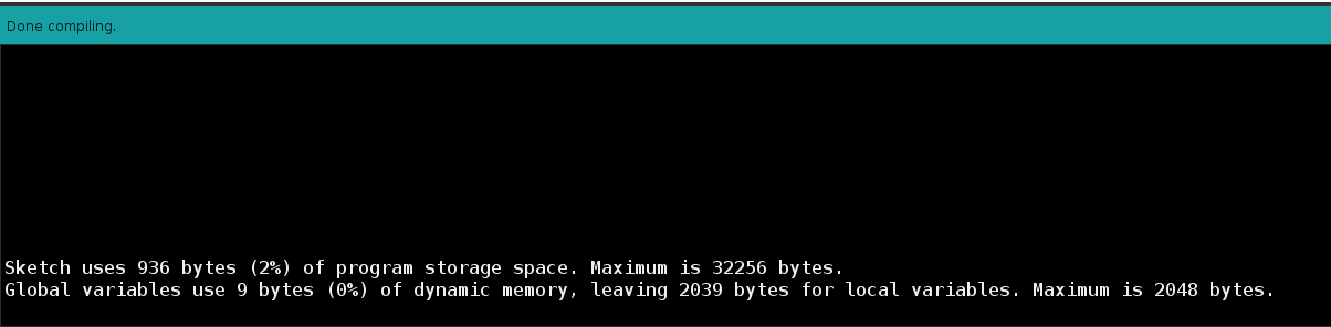
First, we must specify the type of Arduino Board we are using to the IDE. Move your mouse to the Menu Bar and go to tools > board > Arduino AVR Boards > Arduino UNO and select it. If you are using another type of board, then it must be specified here. After doing this, you can verify the sketch to make sure that there are no errors. The IDE also prints out the amount of space your program and variables take on the Arduino, as shown below.
Next, we must specify the port on which the Arduino is connected. Connect the board to your PC using the USB cable. If this is the first time, it might take a couple of seconds for all the drivers to be downloaded and installed by your operating system. After the drivers are done setting up, you can go to tools > port and you should see a list of ports which you can use. If you are not sure which one is the correct one, disconnect and reconnect your Arduino. The entry which appears solely the second time is the correct one.
After selecting the board and port, you can click the upload button to upload your sketch. If you have not built it yet, this should automatically build it before uploading. Once the upload is complete, the LED on the Arduino should come alive and start blinking.
Conclusion
Arduino is an easy-to-use and flexible platform for exploring electronics and programming. After reading this tutorial and blinking an LED using the Arduino UNO, you should be prepared to write basic programs for the Arduino and learn more from the website. You might now be wondering how to fade its brightness gradually, click here for a tutorial on the same. The sky's the limit!
I hope you found this blog interesting and learnt something new. If you have any queries or feedback, drop them down in the comments below and I will definitely check them out. Good luck and happy hacking!