Arduino Tutorial: Light sensing
By Aditya
/
May 22, 2019
In this blog/tutorial, we will see how to use a Light Dependent Resistor (also called a photoresistor) along with an Arduino as a light sensor and log our readings on to the Serial Monitor. This can be used for many projects, such as an automatic night lamp, or a smart light whose brightness is dependent on the ambient light level. We will see how to use an LDR directly and in the form of a breakout board. Let's get started!
What is the behaviour of a light dependent resistor (LDR)?
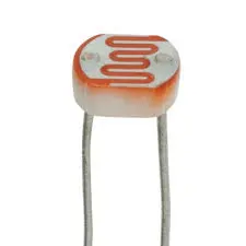
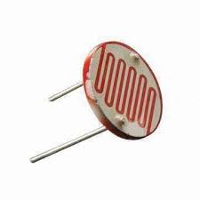
An LDR has two pins, the resistance between whom reduces as the intensity of light falling on its surface increases and vice-versa. The resistance is bi-directional (unlike a diode), i.e. the LDR can be connected any way in the circuit that it is used in.
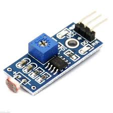
Sometimes, they also come as a part of a breakout board. In this case, the LDR has additional electronics connected to it to convert its output to a digital signal. Their are two pins to provide power to the circuit (VCC and GND) and a third pin which outputs this signal. The signal is normally a logical low value, but goes HIGH when the threshold of light goes above a certain threshold. The threshold can be changed by using the potentiometer (blue box with white "+" dial) on the board.
Now that we have seen how an LDR can be used to measure brightness, let us see how to use it with an Arduino and output its readings to the Serial Monitor.
Gathering the parts
In this step, I will be listing all the parts which you will need for the project.
- Arduino UNO (or equivalent microcontroller) and USB cable (for programming)
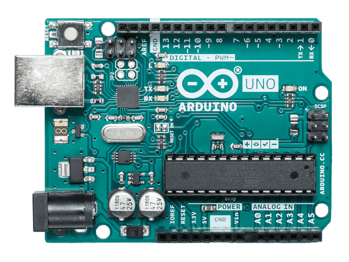
Arduino UNO 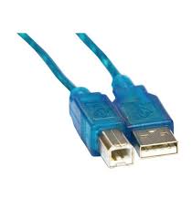
USB programming cable - LDR/photoresistor
Photoresistor with digital output Regular photoresistor - 10K resistor (or +-20%, i.e. between 8K and 12K)
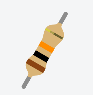
10K resistor diagram (brown-black-orange) - 3/5mm LED (optional, for visualizing output)
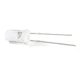
5mm LED - Breadboard (for connecting all components)
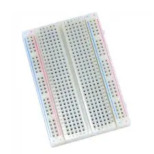
Mini Breadboard
The size of the LDR you are using does not matter for this tutorial. For this tutorial, we will see how to use both the digital and analogue versions individually.
The LED and breadboard are optional. By using the breadboard, it becomes easier to connect all the components together. The LED is there to supplement the data that we will log to the Serial Monitor.
Building the circuit (analog version)
In this step, we will see how to connect an LDR without a breakout board to the Arduino. If you want the connections and code for the digital version, go to the next step. An LED can optionally be used here.
First, connect one of the sensor's pins to 5V/VCC and the other to one of the analogue input pins (I have used A5). The circuit will not work if you do not use an analogue input pin. You can then connect the LED to one of the PWM capable pins on (I have used 5). If you are not familiar with PWM, click here for a good guide/tutorial.
Finally, take a resistor and connect one of its ends to GND and the other to the same analogue input as the LDR. Shown below is how the circuit should look.
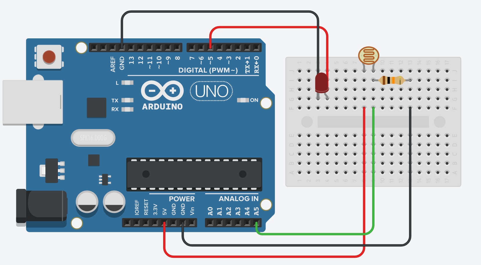
This circuit creates a voltage divider circuit with the LDR. The Arduino's analog input pins can not directly measure the resistance of the LDR. They can only measure the voltage at that pin (with respect to the ground and 5v). Therefore we can create this circuit where the voltage across the LDR is made to vary (within limits, by the use of the second resistor). As the resistance of the LDR decreases, so does the voltage across it, and as it increases, so does the voltage. This can be now be measured by the Arduino. If you wish to read more about voltage dividers, click here.
After finishing the program, you can try to change the value of the resistor and see how this affects the behavior of the program and values being logged to the Serial Monitor.
Building the circuit (digital version)
In this step, I will be showing the connections for the digital version of the sensor with the control board, if you want the connections and code for the regular version, go back to the previous step.
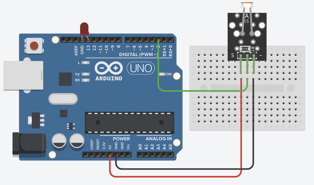
Connect the VCC or 5v pin of the sensor to the 5v pin of the Arduino and the GND pin of the sensor to any GND pin on the Arduino. Next, connect the output pin of the module to any other pin on the Arduino (all pins of the Arduino are capable of digital input). I have used pin 2. Similary, connect the LED to any other pin on the Arduino. I have used pin 13.
Writing the program (analog version)
In this step, we will be writing code to use an LDR without the breakout board. If you want the code with the breakout board, go to the next step. If you are not familiar with writing programs for the Arduino, you can click here for a beginner's tutorial.
Start by creating two constants to store the pins we are using for the LDR and LED as shown below. I have used the names sensePin and ledPin for these respectively. Make sure to use the same values as the ones you have used while building the circuit.
Next, declare sensePin as an input and ledPin as an and initialize the Serial Interface, as shown below. If you are not familiar with the Arduino's Serial Monitor and library, click here for a guide on the same. I have used 9600 for the baud.
Next, we have to read the voltage of sensePin. To do this, we can use the Arduino's analogRead function. This function returns a number between 0 (inclusive) and 1024 (exclusive) that represents voltage values from 0 to 5v. Enter the following code in the main loop.
First, we read the state of sensePin and log it on the Serial Monitor. We also use the analogWrite function to write this value to the LED. The analogWrite function only accepts values between 0 and 255, and we can map the range 0 to 1024 to this by dividing it by 4. The brightness of the LED should now be proportional to the light level on the LDR. After this, your completed code should look as follows.
A delay is added at the end to slow down the printing to the Serial Monitor so that it does not get flooded and unreadable.
You can verify and upload this program to the Arduino. After the upload process is complete, you can open the Serial Monitor to see the value being printed to the Serial Monitor. You can shine a light on the LDR or cover it with your hands/cloth to see this value change. You can also change the value of the resistor we have used to see how it affects the sensor (increase/decrease sensitivity, etc.)
Instead, if you wanted the brightness of the LED to increase as the surrounding light level falls (and vice-versa), then you could subtract the value from 1024 to invert it before writing it via analogWrite, as shown below.
When the surrounding brightness is at its peak (1024), the LED is off (0) and when the surroundings are completely dark (0), the LED is completely on (0). All values in between are smoothly mapped. We still have to divide it by 4 to map the range of analogRead to analogWrite.
Writing the program (digital version)
In this step, we will be writing code to use an LDR with the digital breakout board. If you want the code with the breakout board, go to the next step. If you are not familiar with writing programs for the Arduino, you can click here for a beginner's tutorial.
Start by creating two constants to store the pins we are using for the LDR and LED as shown below. I have used the names code and ledPinfor these respectively. Make sure to use the same values as the ones you have used while building the circuit.
Next, declare sensePin as an input and ledPin as an output and initialize the Serial Interface, as shown below. If you are not familiar with the Arduino's Serial Monitor and library, click here for a guide on the same. I have used 9600 for the baud.
Next, we have to read the voltage of sensePin. To do this, we can use the Arduino's digitalRead function. This function returns the logic-level of the pin it is given according to the input voltage. Enter the following code in the main loop.
First, we read the state of sensePin and log it on the Serial Monitor. We also use the digitalWrite function to write this same value to the LED. The LED switches on when the sensor outputs a high signal and switches off when the sensor reports a low signal. After this, your completed code should look as follows.
A delay is added at the end to slow down the printing to the Serial Monitor so that it does not get flooded and unreadable.
You can verify and upload this program to the Arduino. After the upload process is complete, you can open the Serial Monitor to see the value being printed to the Serial Monitor. You can shine a light on the LDR or cover it with your hands/cloth to see this value change. You can also control the sensitivity of the sensor by rotating the potentiometer's dial and see how this affects the readings.
Instead, If you wanted the LED to switch on when the light level becomes too low (and vice-versa), you could invert the value being written via digitalOut, by using the following code.
The exclamation mark before val is used to invert its logical value, i.e. make it HIGH if it is LOW and LOW if it is HIGH.
Conclusion
After reading this blog, you should have a better idea of using photoresistors with an Arduino and how simple it is. You can use this knowledge to start working on an automatic night lamp that switches on automatically when it gets dark, or a smart light that changes its brightness based on the ambient light to conserve power. The sky's the limit!
I hope you found this blog interesting and learnt something new. If you have any queries or feedback, drop them down in the comments below and I will definitely check them out. Good luck and happy hacking!