Using the Arduino UNO R4 LED Matrix to Build the Pong Arcade Game
By Aditya
/
August 21, 2023
Arduino has just released the latest addition to UNO family with the UNO R4 Wifi and Minima. This blog focuses on one of the new features of these boards, which is the 12x8 LED Matrix. We will see how to use the LED Matrix to display simple graphics, move onto animations, and tie this all together by building the famous Pong Arcade Game. Let's get started!
This blog assumes that you have set up the Arduino IDE to be able to program the UNO R4. Alternatively, you can also use the Web Editor which removes this setup step altogether. Beginners who wish to get started with the Arduino IDE can click here (this tutorial uses the UNO R3, but the UNO R4 works just as well). To instead get started with the Web Editor, click here.
Note - The 12x8 LED matrix is only available on the Arduino UNO R4 Wifi, and not on the Minima version of the board.
Using the LED Matrix with the builtin library
In this section, we will how to display simple graphics and animations on the LED Matrix with the builtin library. This library is included by default in the Web Editor, and is automatically installed along with the board support packages for the UNO R4 in the desktop IDE. In order to use it, we must include the Arduino_LED_Matrix.h file into the sketch, as shown below.
After including the library, the first step is to create an object of the ArduinoLEDMatrix class, and initialize it in the setup function, as shown below.
The library controls the matrix by showing frames that are given by the programmer. A frame is a static image that can be shown on the matrix at any point of time. To display a video/animation, multiple frames are displayed in quick succession. The matrix object has two ways to accept a single frame to display. The first is through the renderBitmap method, which accepts a 2D boolean (0 or 1) array of size 12x8, where each element of the array corresponds to a single pixel at the same location. For example, the code shown below can be used to create a heart on the matrix.
The second way to render something on the matrix is by using theloadFrame method, which accepts an array of three 32-bit integers. This may seem odd, but starts to make sense when you consider that each pixel requires only a single bit to define its state, i.e. 8*12 = 96 bits are required, and 3*32 bits = 96 bits, which is the exact number of bits required. The same heart, for example, can be displayed using the loadFrame method as shown below.
In particular, notice how the numbers of the array have a ob prefix, which denotes that they are represented in binary notation, rather than the regular decimal notation.
A detailed explanation of the loadFrame method can be found here. TherenderBitmap method is a lot more intuitive and human-friendly than the loadFrame method, but uses more storage. This should not be a problem in most projects (due to the generous 256 kB of storage present on the UNO R4), but in certain cases where a lot of frames need to be used, the loadFrame method comes in handy.
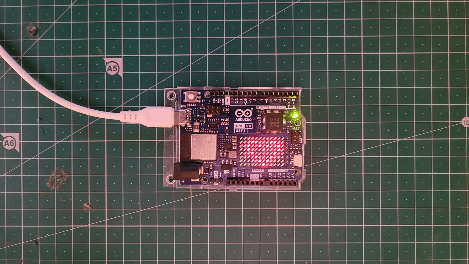
The library also provides the ability to load your own frames into a buffer and play them as an animation, concurrently with the rest of the program, similar to how your computer could be running a Web Browser (allowing you to read this blog), and a text editor at the same time, without either of the programs affecting the other. This is illustrated below.
On running the program, is becomes apparent that the code within the loop function is executed at the same time as the animation, i.e. "Hello World" is being printed on the Serial Monitor every second at the same time as the frames being rendered. Each frame in the animation is defined by four numbers. The first three numbers (represented in hexadecimal notation with 0x prefix) represent the state of the pixels similar to the loadFrame method, and the fourth number denotes the duration of the frame (in milliseconds).
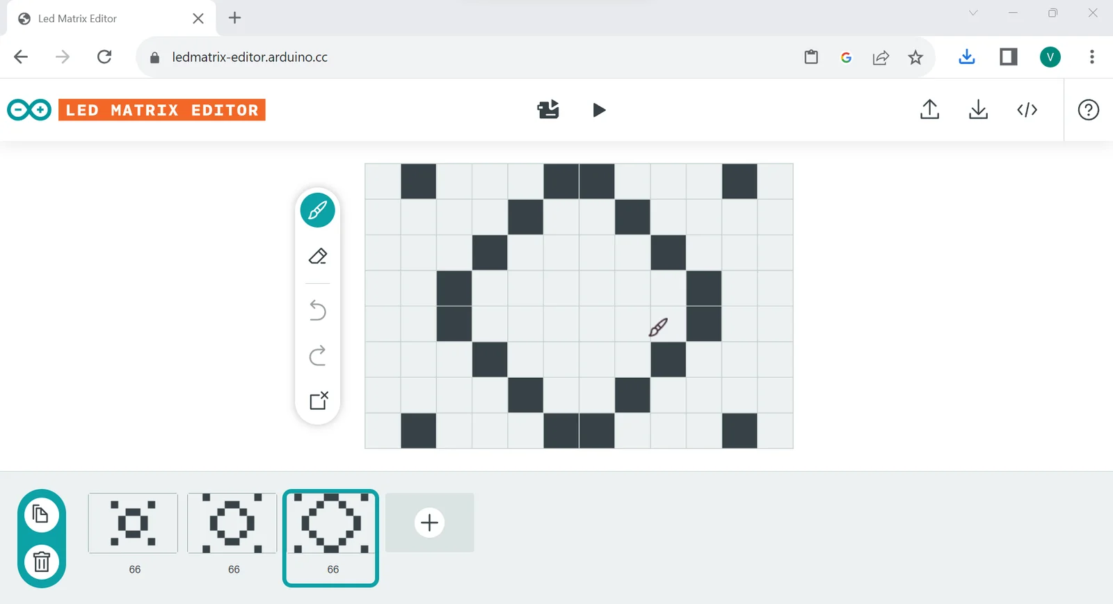
Arduino has also created an online tool called the LED Matrix Editor (click here), to make frame-creation easy. Each frame can be graphically edited and given a duration. After this process is complete, simply give a name for the file and download it for use within your project. For example, the animation shown above looks as follows.
Creating the Pong arcade video game
In this section, we will use the learning from the previous section and create the famous "Pong" Arcade game using the Arduino UNO R4 LED Matrix and a Potentiometer. We will start with the parts required, move onto building the circuit, and conclude by writing the program and uploading it to the board. In this example, we will build a single-player version of the Pong game due to the limited size of the LED Matrix. A two-player version can be implemented, but is left as an exercise for the reader.
For those unfamiliar, Pong is a simple arcade game consisting of a Paddle/Platform and a ball. The ball moves on the 2D screen in straight lines. Whenever it hits either of the bottom, left or right edges, it bounces with a random return angle. The top edge is controlled by the player, who can move the paddle along it. The goal of the game is to make sure that the ball does not hit the top edge, and bounces off the paddle instead. If the ball misses the paddle and hits the edge, the game ends.
In particular, the speed of the ball would increase after every bounce to keep the game fun, and the direction of the ball would be randomized after each bounce, instead of simply following a 90-degree reflection. Due to the constrained dimensions of the matrix, this behavior would look fairly jittery and is therefore not implemented.
Components required and assembling the circuit
In this step, we will see the hardware components that are required to build the game and assemble its circuit. The components required to build the circuit are shown below -
- The Arduino UNO R4 WiFi
- USB Type-C Cable
- 10K potentiometer
- Connecting Wires
- Breadboard
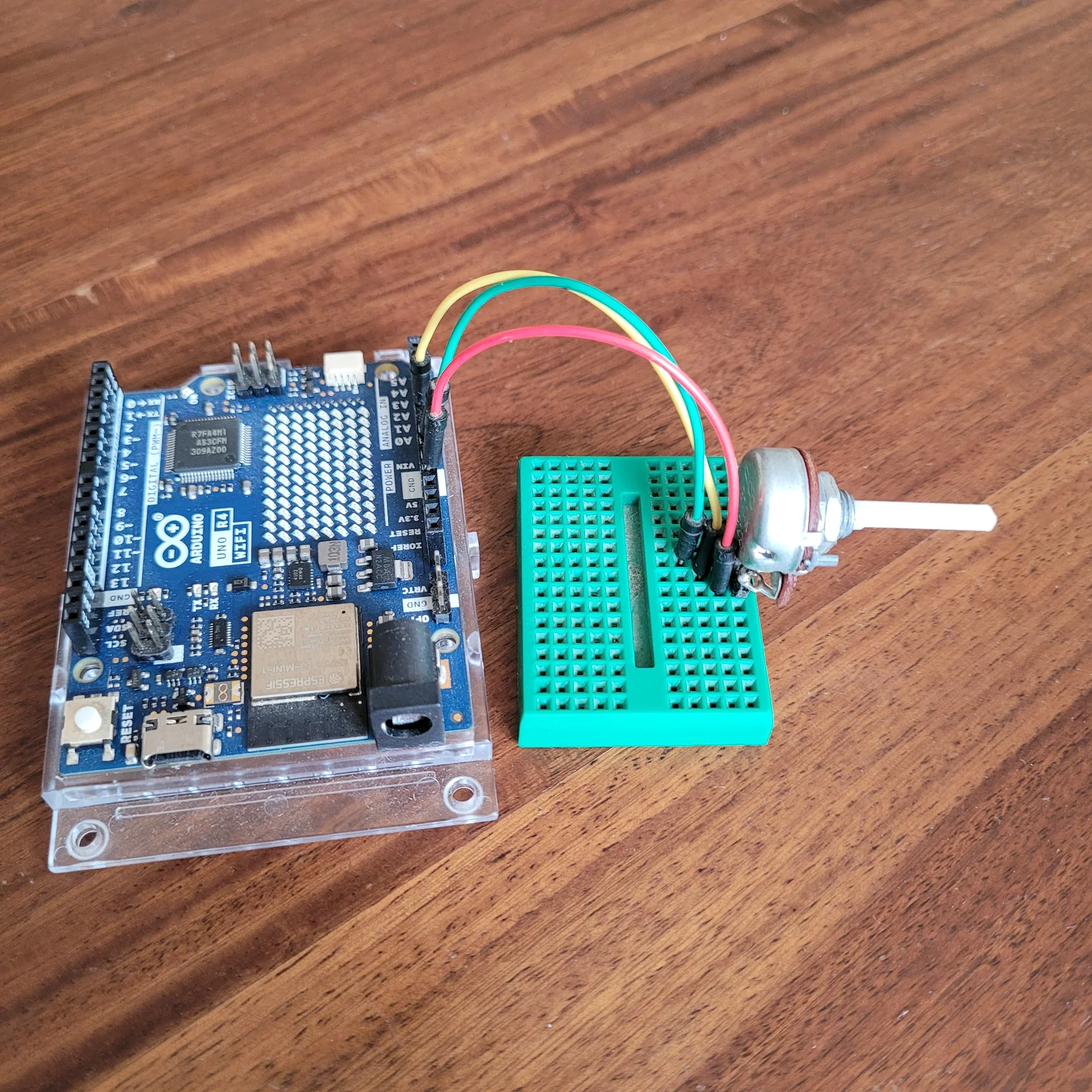
The completed circuit, along with the connections, is shown below -
| Arduino pin | Potentiometer pin |
|---|---|
| 5v | 1 |
| GND | 2 |
| A0 | 3 |
It is a fairly simple circuit, where the potentiometer is used as a variable voltage divider for the Arduino. One leg of the pot connects to ground, while the other connects to 5v. In this configuration, the middle leg supplies a voltage between 0 an 5v, depending on the angle of rotation of the pot. The Arduino reads this value as a value between 0 and 1023. Therefore, by turning the knob of the pot, we can control the position of the paddle.
Writing the program for Pon
In this step, we will write the program for Pong. the first step is to define some constants for the dimensions of the matrix, the pin on the Arduino which the pot connects to and the duration between two movements of the ball.
The exact usage of these constants will become clear as we see the rest of the program. The next step is to include the Arduino_LED_Matrix.h file and instantiate an ArduinoLEDMatrix object.
Next, we create variables to hold the states of the paddle, ball, matrix and an end-game screen.
The array grid will be used to store the instantaneous frame being shown on the matrix. The array over is used to store the word "END", which is displayed once the game has ended. The array ball_pos is used to store the horizontal and vertical coordinates of the ball while the array ball_vel is used to store the horizontal and vertical velocities of the ball (every frame, the velocity of the ball is added to its position). The variable platform_pos is used to store the horizontal coordinate of the paddle on the matrix (the paddle remains on the top of the matrix and does not need a vertical coordinate). The variable pot_val is used to hold the value of the pot each time that it is read.
The next step is to declare the potentiometer pin as an input pin, and initialize the matrix. This is done within the setup function.
Next, add the following code within the loop function to update the position of the paddle on every iteration.
This code first removes the paddle from its previous position, i.e. where it was in the previous iteration. It then reads the value of the pot, and maps the value to a coordinate between the left and right bounds of the matrix, which is used as the updated position. The paddle is then added at its new position. This ensures that paddle follows the movements of the potentiometer at all times. If the pot was not moved at all, the paddle is removed from, and added to the same location, effectively not moving it at all.
The next step is to update the position of the ball based on various conditions. Add the following code within the loop function.
Let us look at this code step-by-step. The outermost if-condition is placed to limit the rate at which the ball is updated. It ensures that the duration between two consecutive updates to the ball is atleast FRAME_PERIOD milliseconds. This done by storing the timestamp of the previous frame and comparing it to the current timestamp. If the gap is sufficient, the code moves forward and updates the timestamp of the previous frame.
The lines that follow update the position of the ball in a similar manner to that of the paddle, i.e. it is removed from its old position, its new position is calculated using its velocity, and it is finally added back to its new position. Following this, we check if the ball has collided with any of the four edges.
First, if the ball has collided with the vertical (right or left) edges, then its horizontal velocity must be reversed whilst maintaining its vertical velocity.
If the ball has collided with the bottom edge, its horizontal velocity must be reversed whilst maintaining its horizontal velocity.
Otherwise, if the ball has collided with the top edge, the game has ended and the end-screen is displayed.
Lastly, if the ball is approaching the top edge, but collides with the paddle, then its vertical velocity is once again reversed.
These clauses ensure that the ball follows the laws of reflection, and also handles all edge-cases, such as when the ball hits a corner (two edges simultaneously), or when it hits both the paddle and a vertical edge.
Finally, add the following code within the loop function to render the grid at the end of each iteration. a small delay is added to limit jittery movement of the paddle.
The complete code is shown below -
After verifying and uploading this code to your Arduino UNO R4 Wifi, the game should start immediately. If the paddle movement is jittery, make sure that the potentiometer is firmly connected to the Arduino, as a loose connection might pick up electrical noise from the environment and cause the Arduino to read junk values.
Final Thoughts
After finishing this tutorial, you should be confident on using the LED Matrix on the UNO R4 and have the Pong game ready. If you found this blog useful, or have any questions or feedback to share, leave it in the comments down below, I'd love to know them!
Additional Resources
- Getting started with the Arduino UNO R4 Minima on the desktop IDE by arduino.cc
- Getting started with the Arduino UNO R4 Wifi on the desktop IDE by arduino.cc
- Getting started with the Arduino UNO R4 LED Matrix by arduino.cc
- Arduino UNO R4 LED Matrix Editor by arduino.cc
- Getting started with the Arduino UNO R4 Wifi networking capabilities by arduino.cc
- Buy the Arduino UNO R4 Minima from arduino.cc
- Buy the Arduino UNO R4 Wifi from arduino.cc