How to get started with Arduino using the Web Editor for beginners
By Aditya
/
April 2, 2023
In this tutorial, we will see how to get started with Arduino using the Web Editor, Create Agent and UNO board by blinking an LED. This guide can by read by beginners, who are new to electronics and programming, or by those already familiar with Arduino and are wanting to use the Web Editor for their projects. After reading this guide, you should be equipped to explore and learn Arduino on your own, and build projects with increasing complexity.
This guide starts with an overview of the Arduino platform, and shows how to choose an Arduino Board for your requirements. It then explains the software used to write programs for an Arduino and components used to build circuits with Arduino. Finally, it shows example programs and circuits for blinking an LED, fading an LED and using pushbuttons with the Arduino UNO and Web Editor. After reading this blog, you should be familiar with the basics of Arduino, and equipped to learn more on your own. Let's get started!
Getting started with the Arduino platform and choosing a board
In this section, we will go over what the Arduino platform is all about and how to choose a board for your project (or for getting started with electronics). If you are already familiar with this, you may skip to the next section. Beginners may find it a little overwhelming to understand all of this in one-go, and can simple purchase an Arduino UNO R3 and get started; coming back to this section after completing the rest of the tutorial.
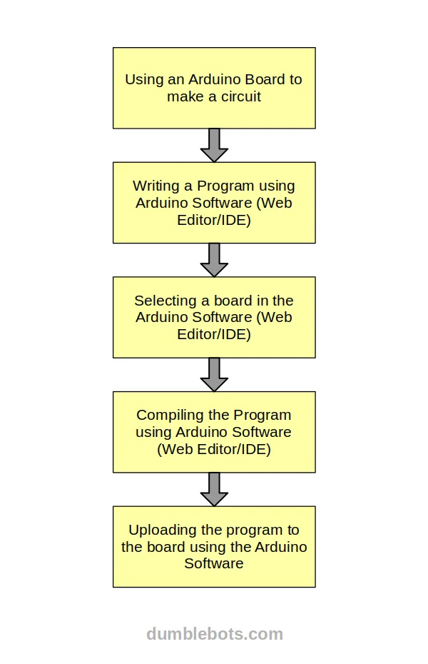
Arduino is a flexible and open-source platform for learning electronics and programming. It consists of hardware (boards and shields), software (the Arduino programming Language that is based on C++) and a forum to discuss doubts. To allow development using the Arduino Language, an Integrated Development Environment (IDE), Web Editor and CLI tools is also included. A typical workflow for developing Arduino programs is shown below -
More recently, they have also started including cloud services as part of their suite. You can click here to read more about this. To summarize, the platform may be used by hobbyists, tinkerers and makers of all sorts to develop their projects.
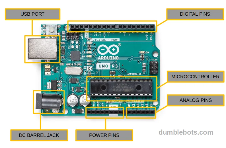
All Arduino Boards contain a microcontroller that acts as the brain of the board. It also contains some other components necessary to drive the microcontroller such as a voltage regulator, resistors etc. Advanced boards may also have Wifi/Bluetooth modules, SD card slots etc. All of these components are soldered onto a single circuit board (along with a USB port to connect it to your PC). Finally, the microcontroller's IO pins are "broken out" in the form of pins for convenient usage with wires and breadboards. A labelled diagram of the Arduino UNO is shown in the next section.
Programs can be written and uploaded to the Arduino to control its behaviour and hardware. Using this, we can make the Arduino perform input (read voltages/signals/sensors) and output (generate signals, output voltages, drive a motor etc.) By using the peripherals within the microcontroller, we can also perform more advanced tasks such as time measurement, or communicate with and control components such as cameras or displays, to name a few. Projects in the Arduino ecosystem are called sketches. A sketch includes the program files along with some other files that may describe the project and its target board.
As of writing this blog, the boards offered by Arduino are divided into the following families. A family includes boards that have similar form factors and features, with minor differences for their specific use-cases.
- Classic Family - This includes Arduino Boards that use 8-bit AVR microcontrollers running at low clock frequencies. They lack fancy features such as multiple cores, connectivity and built-in sensors, but make up for this in simplicity of use. This makes them ideal for beginners getting into electronics or for extremely simple and low-power applications.
- Nano Family - This includes Arduino Boards that are smaller with more powerful 32-bit ARM Cortex microcontrollers. They may possess multiple cores, Wifi/Bluetooth/BLE connectivity options and sometimes include built-in sensors. Consequently, they are usually more expensive than the classic boards. They are well suited for more advanced embedded applications that require more computing power, multitasking or an RTOS etc.
- MKR Family - This includes Arduino Boards that are focused on connectivity with support for various wireless protocols such as Wifi, GSM, Bluetooth/BLE, Radio, LoRA etc. They too use powerful 32-bit ARM Cortex microcontrollers, and are slightly larger than the nano boards, but are still smaller than the classic boards. Their prices lie between the Classic and Nano Families.
- Portenta Family - This is a later addition to the families of Arduino boards and consists of industry-ready boards. They use powerful microcontrollers geared towards computationally intense applications along with rugged components designed for production-grade reliability. Consequently, these are non-trivial to use properly and are quite a bit more expensive than the other families. They are not recommended for beginners.
- Nicla Family - This too is a later addition to the families of Arduino boards, and is geared towards machine learning and advanced sensor applications in environments with tight power and space constraints.
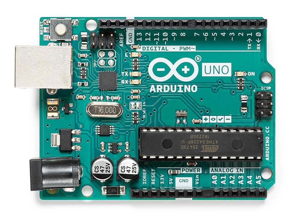
This blog uses the timeless Arduino UNO R3 from the Classic Family, as it is commonly agreed to be their most popular, well-documented and robust board, and is best for getting started with electronics and programming. As of writing this tutorial, Arduino has recently released the UNO R4 as well, which adds a powerful ARM processor and connectivity options to the UNO whilst still maintaining its ease of use. After finishing this blog, you may soon find it interesting to get started with it as well.
Using the Arduino Web Editor vs Integrated Development Environment (IDE) for writing programs
In this section, we will have a look at what the Arduino Web Editor is, and compare it to the Integrated Development Environment (IDE). Both tools are quite easy to use for beginners, and it is worth taking a few moments to have a look at their differences. It also briefly covers tools for advanced users, namely the ArduIno CLI and IDE 2. If you are already familiar with this, or wish to directly start with the Web Editor, you can skip this section an back to it after finishing the rest of the tutorial.
The Arduino IDE is the first IDE released by Arduino and is an open source desktop application available on Windows, Linux and Mac OS. Because it an Integrated Development Environment, it includes all the tools necessary for developing Arduino applications in one place, such as the code editor, compiler, programmer, package manager etc. This removes the daunting task of having to setup everything individually. Since it is a desktop application, it can be used offline, and does not require an internet connection as such.
The Web Editor, on the other hand, is a later addition to the Arduino Family and includes an online compiler and editor. Because it runs in the web browser and stores all projects in the cloud, it is possible to work on Arduino projects from anywhere and on any device, without requiring to install any software. Of course, to upload programs, the Create Agent must be installed, but it is still easier to setup than the IDE.
The Web Editor has the most up-to-date support for official boards and libraries, due to receiving its data from the cloud. The IDE, however has better support for third party boards and libraries, since it stores its files locally and it is easier to add packages. Overall, it is a better choice for beginners because of fewer steps required to set it up. Additionally, most beginners do not have to worry about adding support for complicated third-party boards when they start out. That being said, it is still a good idea to get acquainted with the desktop IDE sooner or later. Click here for a guide on how to get started with Arduino the old way.
Apart from the Web Editor and Classic IDE, Arduino also provides the Arduino CLI and IDE 2 (previously called the Pro IDE).
The Arduino CLI is a Command Line Application for developers seeking to use IDEs/editors other than the Arduino IDE. It is a single tool capable of performing all the steps for developing an Arduino Project. Because it is invoked from the command line, it can be integrated with other editors, IDEs and automation tools. The Arduino CLI is oriented towards projects where the Arduino tools are used as a part of a larger build system that also supports other modules in the project.
The Arduino IDE 2, meanwhile, is a newer and more powerful desktop IDE. It has a significantly more modern interface that is akin to modern IDEs. Apart from the standard features available in IDE 1, it has several extra features such as code-completion and live debugging. It is useful for improving productivity in professional environments.
Both the Arduino CLI and IDE 2 are available on Windows, Mac and Linux, and run offline. They are a little more complicated to use than the Web Editor and Classic IDE, but can significantly improve the development experience for advanced users.
Components on an Arduino UNO
In this section, we will look at the components of an Arduino UNO R3 board. Most Arduino boards will share these components, along with some minor differences to account for the specific uses/applications that the board was designed for. If you are already familiar with the components on an Arduino board, you may skip this section. Beginners are encouraged not to skip this section, as it makes understanding the programs a lot easier.
Going in order, we have -
- Microcontroller - This is the brain of an Arduino board and is what stores and executes programs. It has tiny single-core processor along with some storage, memory and some other peripherals.
- Power Pins - These are pins that are responsible for supplying power to various components or the microcontroller. All GND pins are at 0v (just like the negative terminal of a cell/battery) and are used to ground current. Conversely, all 5v and 3.3v pins are at the mentioned voltages, and act as the positive terminal of a cell/battery. Vin can be used to connect an external power supply to the Arduino. Note that certain clone boards might have the 3.3v pin labelled as 3v3 instead. They mean the same thing.
- Digital Pins - These are pins that can read and output digital logic levels. In output mode, they can either be set to a High State (5v on the Arduino UNO, 3.3v on some other Arduino Boards) or a Low State (0v). In input mode, they can be used to read digital signals. Some of the digital pins are capable of analog output as well. Particularly, this is indicated with the tilde (~) symbol before their number.
- Analog Pins - These are pins that are used to read analog signals. On the Arduino UNO, these pins have a 10 bit resolution, i.e. a voltage in the range of 0 to 5v is mapped to a number between 0 and 1023.
Some of the digital/analog pins also have hardware support for communication over protocols such as I2C, SPI etc. Beginners do not have to worry about these at the moment.
The barrel jack on the UNO can be used to power the board from a DC source, while the USB port is used to connect it to a PC for programming. When connected to a PC, it automatically powers the Arduino without requiring an external power supply.
Basic components used to build Arduino circuits
In this section, we will look at some components that are used to build electronic circuits with an Arduino. While the Arduino UNO acts as the primary controller of the system, it needs other components to accomplish useful tasks in the real world. If you are already familiar with electronics circuits, you can skip this section. A brief list of such components is shown below -
- Jumper Wires - Jumper wires (or any other kind of wires) are necessary for connecting components. Jumper wires are special wires that have solid metal pins/holes at their ends. This makes it easy to insert them into an Arduino Board. Jumper wires can also be substituted for solid core wires, which are made of a single, thick piece of metal and are easy to connect to an Arduino. Unlike jumper wires, they maintain their shape once bent.
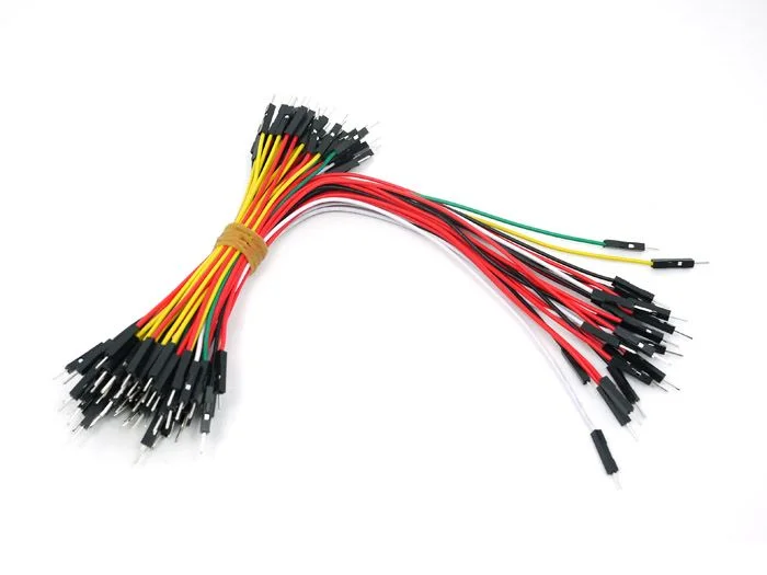
Jumper wires 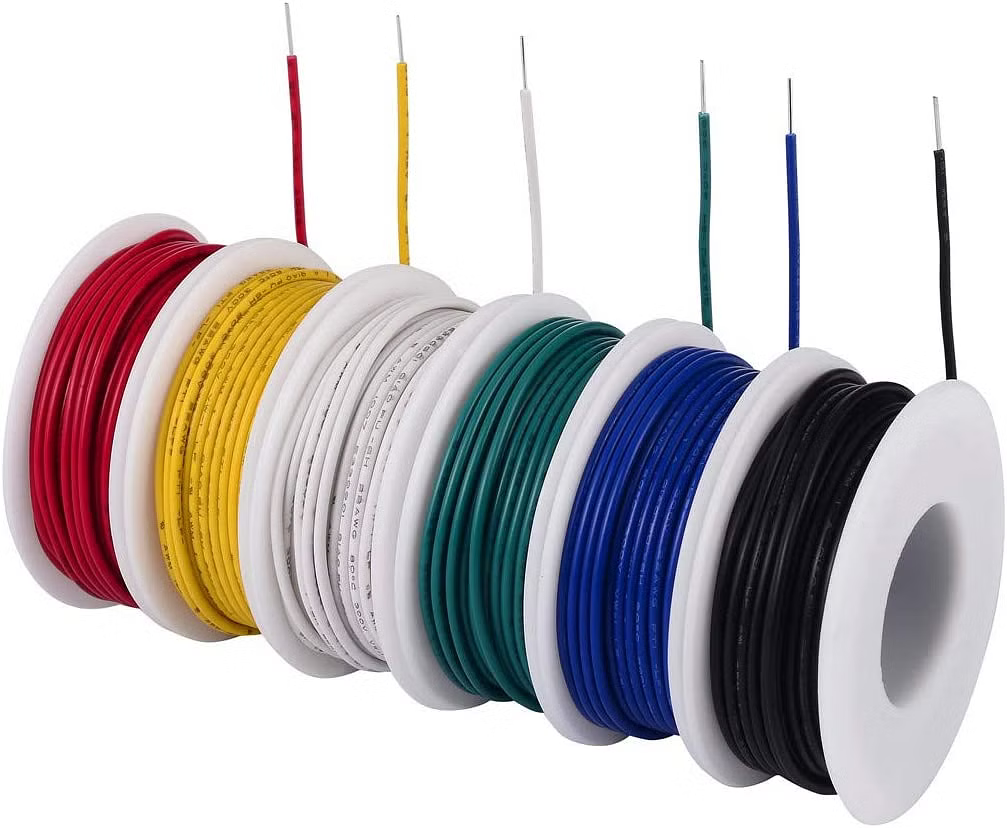
Solid-core wires - Breadboards - A breadboard is perhaps the most important tool for prototyping circuits. It is a rectangular piece of plastic with rows of holes (pins) for inserting ends of wires. Each row is connected internally using a metallic trace. Using this method, the wires can be connected without needing to be soldered or spliced. Furthermore, all breadboards follow a standard placement of pins to make it easy to build circuits on them. Click here to read more about breadboards.
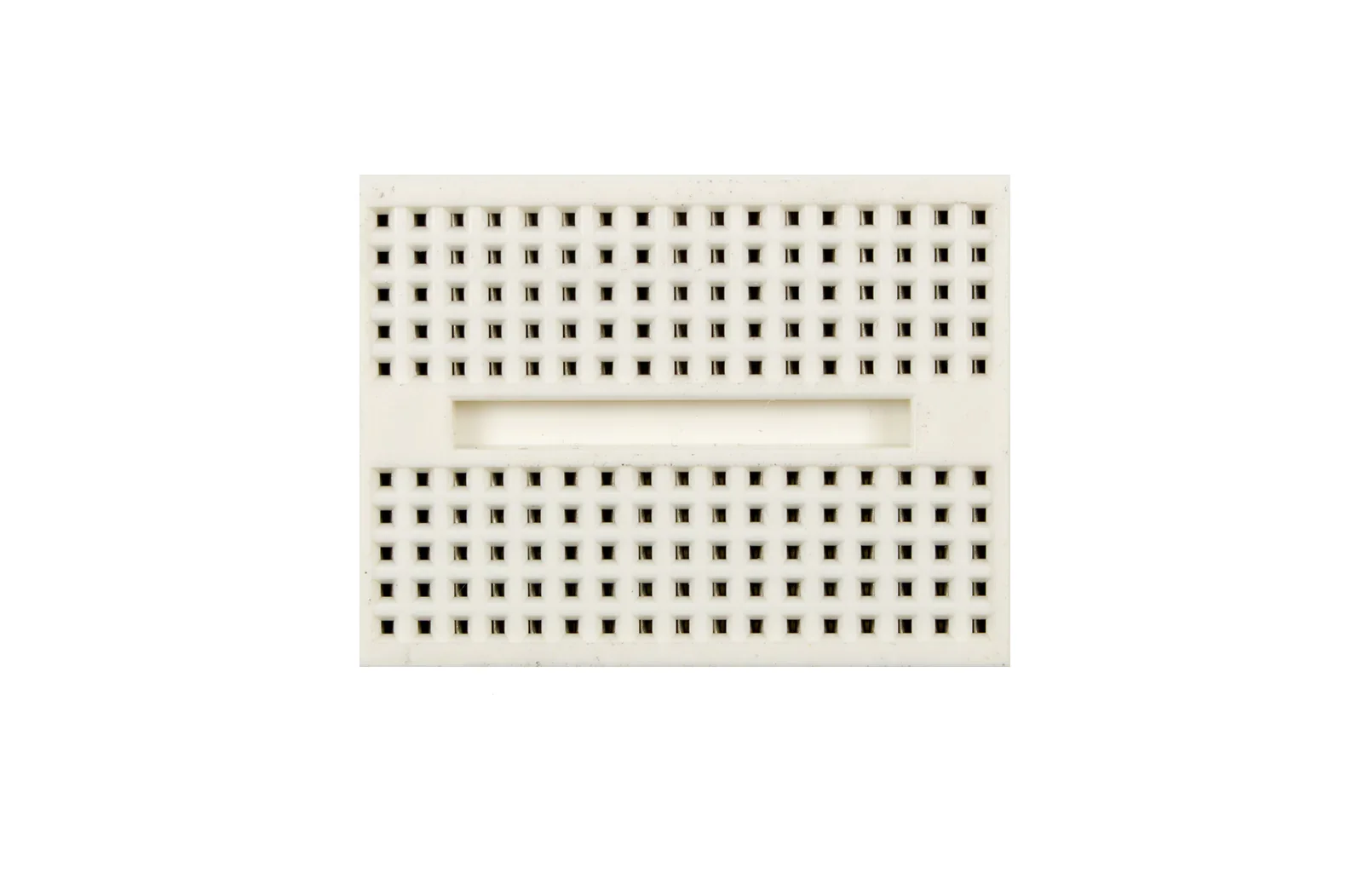
Mini breadboard 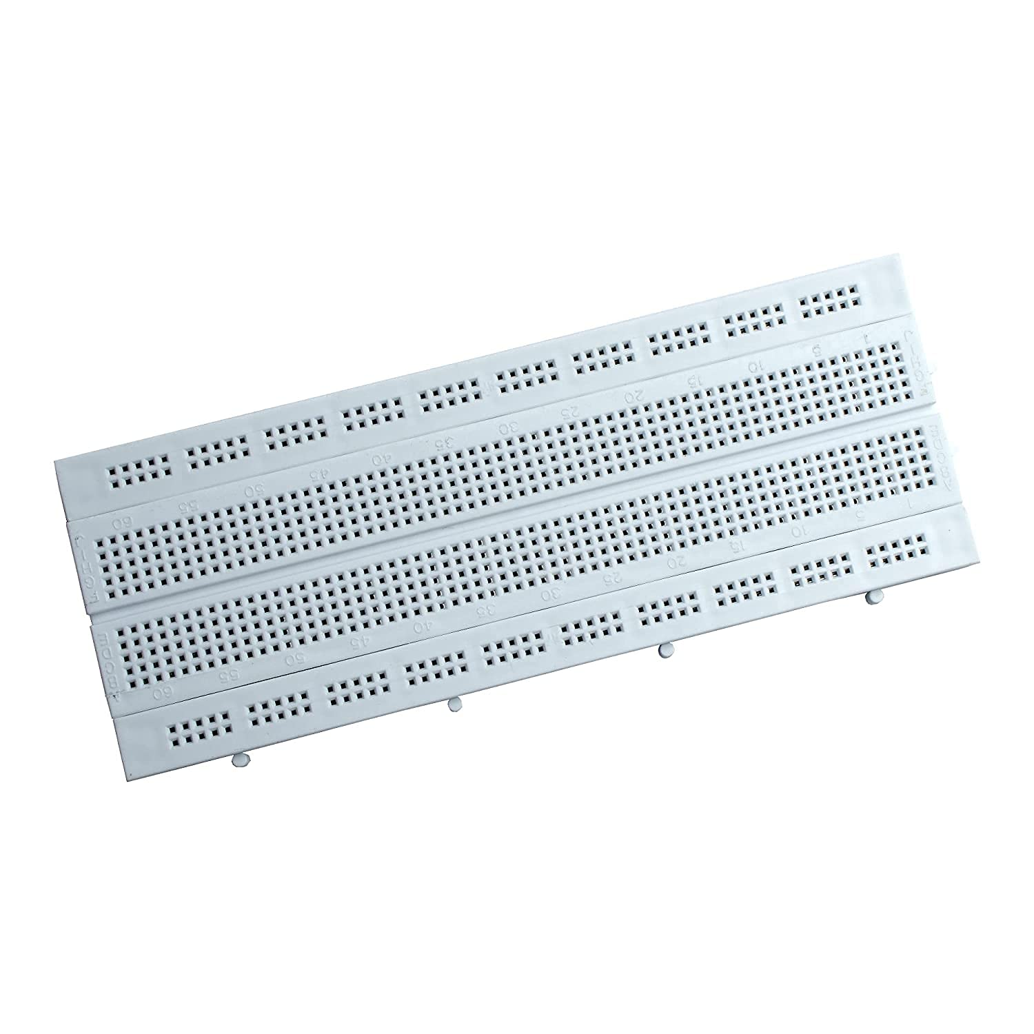
Regular breadboard - Resistors - A resistor is a cheap staple used in electronics circuits. They are components with two pins that limit the flow of electricity. In particular, this can be used to prevent heating or overloads, or to increase the time taken by a component to charge-up.

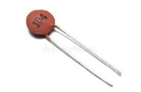
Resistors - Capacitors - A capacitor is an electronic component that can hold charge and energy. They can be used as mini batteries, AC filters and a lot more. Depending on the material they are made of, they can either be ceramic (non-polarised), or electrolytic (polarised).
Ceramic capacitor 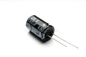
Electrolytic capacitor - Diodes - These are components with two pins that are made out of semiconductor material. They allow current to flow in one direction, but not the other.
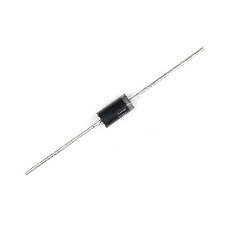
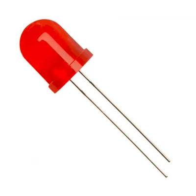
Diode - LED (Light Emitting Diodes) - A light emitting diode is a special kind of diode that emits light when current flows through it.
LEDs - Pushbuttons/Tactile Switches - These are simple buttons, i.e. they have two contact points to connect wires to. While the button is being held down, the contacts are shorted together. They are momentary, i.e. the connection only persists for as long as the button is held down, and the contacts are disconnected once the button is let-go.
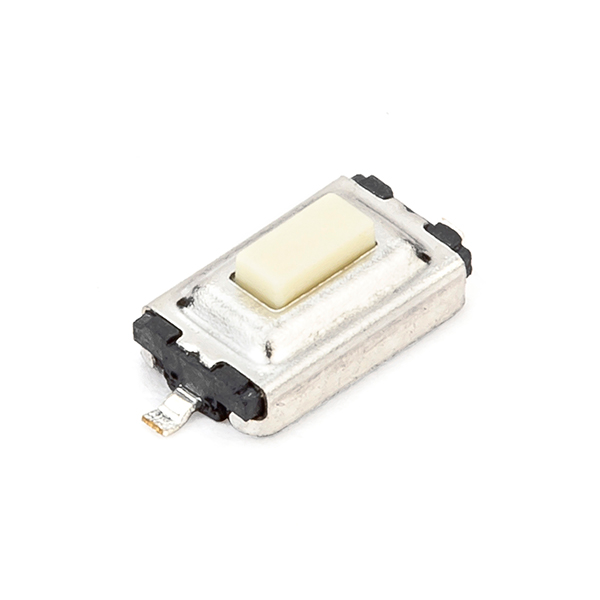
Pushbutton (single pole) 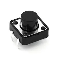
Pushbutton (double pole)
We will use some of these components along with the Arduino UNO to build circuits in the coming sections. We will then program the Arduino using the Web Editor to make the circuit functional.
Setting up the Web Editor
In this section, we will see how to setup the Web Editor and Create Agent for programming Arduino Boards.
Signing in to the Web Editor using Arduino Create
The first step to write code in the Arduino Web Editor is to sign-in with your Arduino Create account. You can either create the account manually, or use one of the following account providers to bootstrap it -
- Github
- Apple
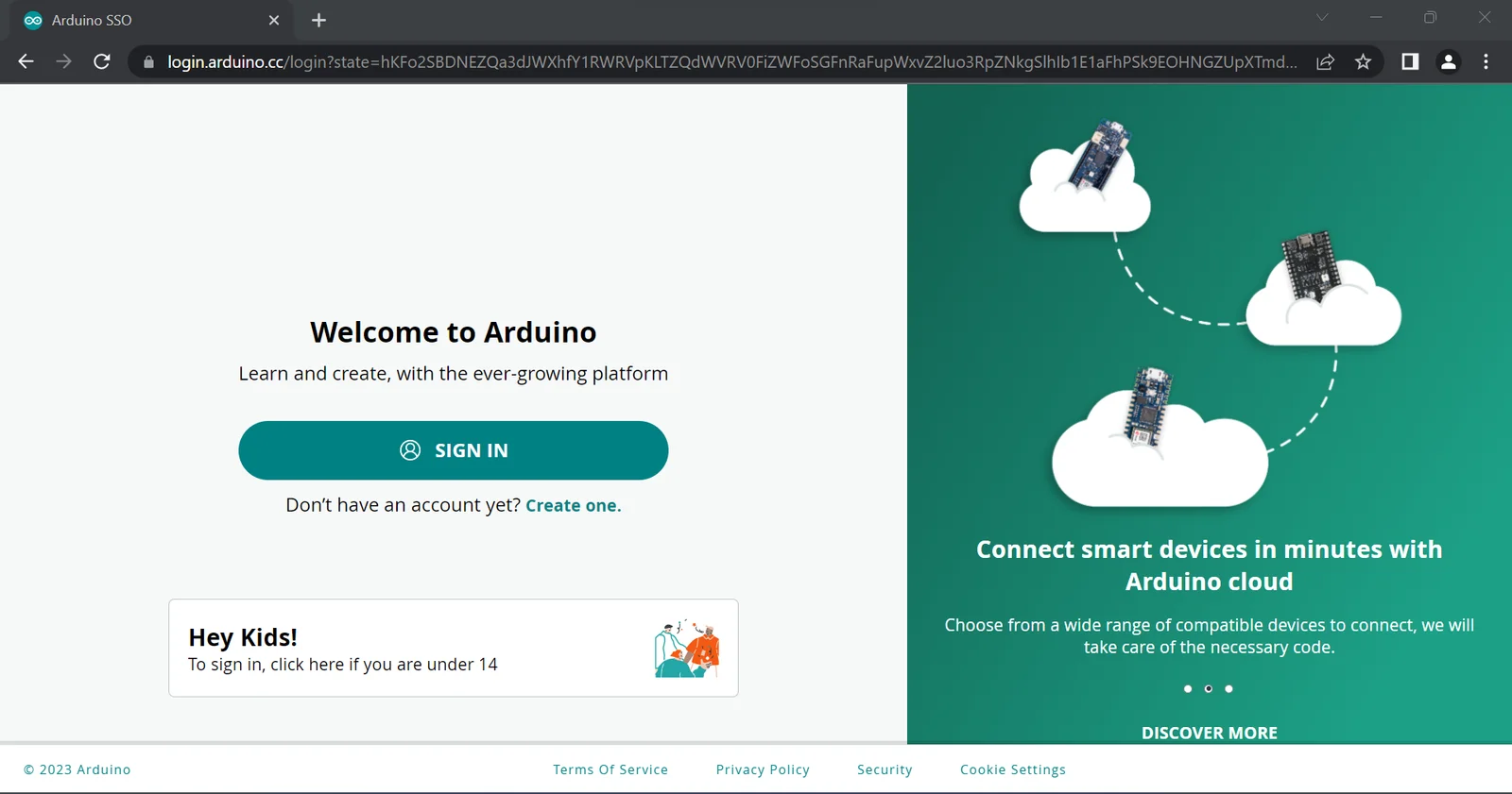
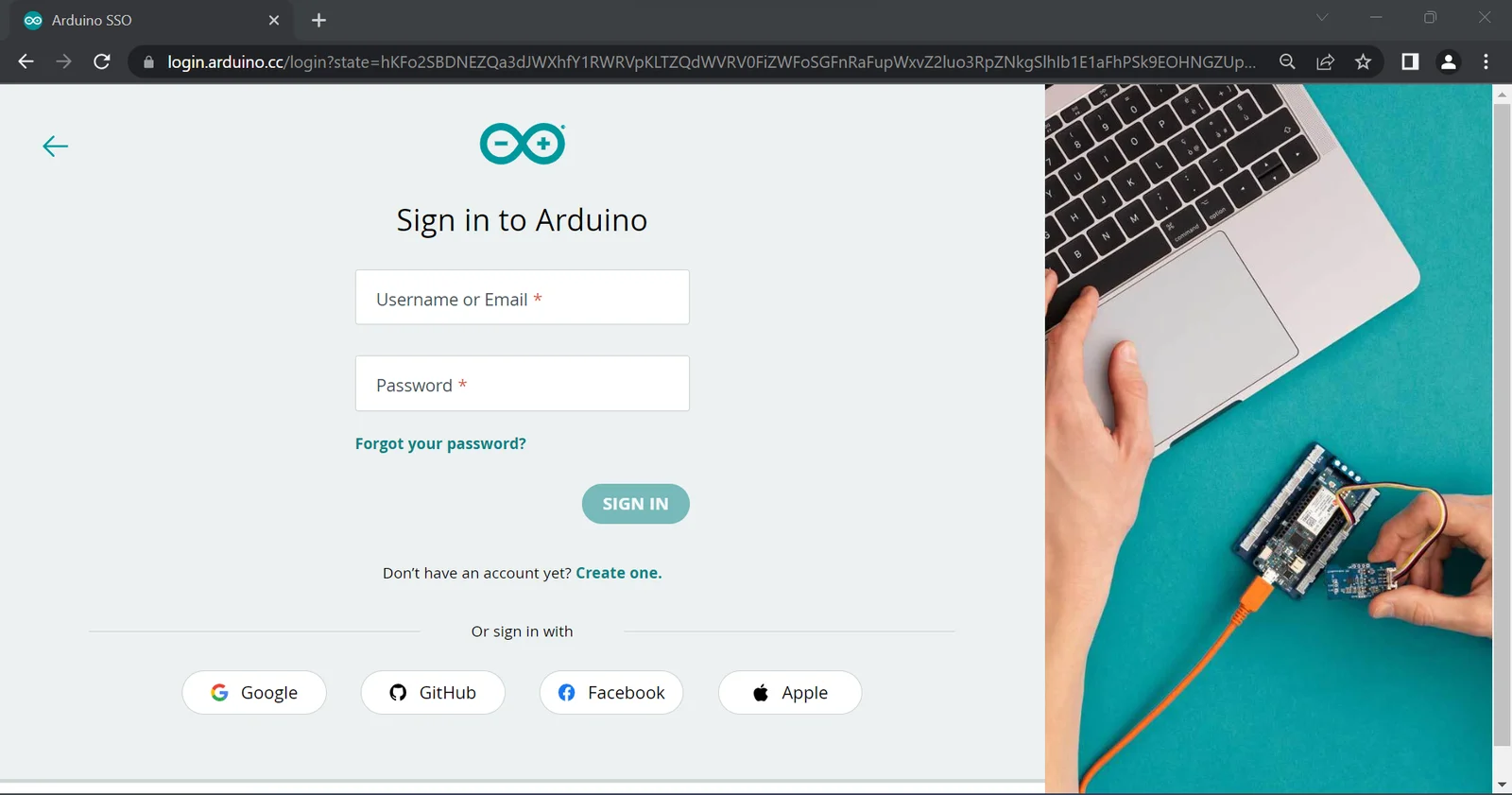
Make an account with either of the above and go to create.arduino.cc/editor. You should be greeted with the following screen, prompting you to either sign-in or create an account. Click on the SIGN IN button to open the sign-in page.
After signing in, you should be taken to the web editor, as shown below. I have used the dark theme on the editor, and it may appear with a different color scheme to you.
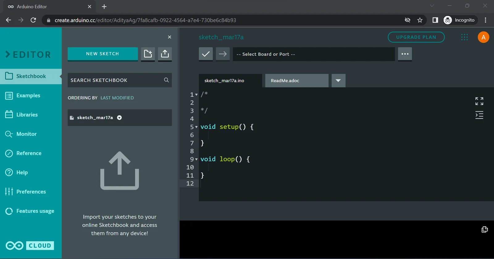
The Web Editor Interface has several columns. Let us see them one by one -
- The first column allows you to navigate through the features made available in the Web Editor, i.e. examples, libraries, the Serial Monitor, reference, etc. The default option selected is the Sketchbook. This shows a list of all the sketches created in the Web Editor. As mentioned before, a sketch comprises of a full Arduino Project, that includes the program files and other files that describe the project and source code etc. The rest of the options are covered in a bit.
- The second column shows information according to the option that was selected in the previous column. In case of the Sketchbook, it shows buttons to create a new sketch (leftmost), creating a new folder in the cloud (middle), and importing a locally saved sketch that could have been created by the desktop IDE (rightmost). Creating folders is in the Web Editor similar to creating folders locally. They can contain sub-folders and sketches within them. Below this is a list of sketches and folders, along with the topion to search through them.
- The third column is the code editor itself. Only one file is open at a time and all the files are displayed as tabs above the editor. By default, the file with the .ino extension should be opened. In the Arduino platform, all files with the .ino extension are source-code files. Apart from this there may be some text files where you can document and describe your project. Above the editor are buttons to verify (tick mark) and upload (right-facing arrow) the current sketch. Next to this is a dropdown to select the board being developed for, and the port it is connected to. This will be explained in the coming sections.
If this is the first time opening the Web Editor, a default sketch is created and named using the current date. The "a" suffix is present in the name in order differentiate between multiple sketches that were created on the same date.
Setting up the Create Agent
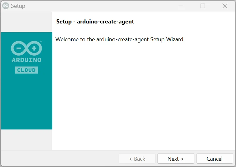
The Web Editor on its own is enough to write and edit programs, but needs a special program to be able to communicate with Arduino Boards connected to your PC, called the Create Agent (also called the Web editor Plugin). To install it, go to https://create.arduino.cc/getting-started/plugin/welcome. You should be greeted by the Arduino Create Agent Installation Page.
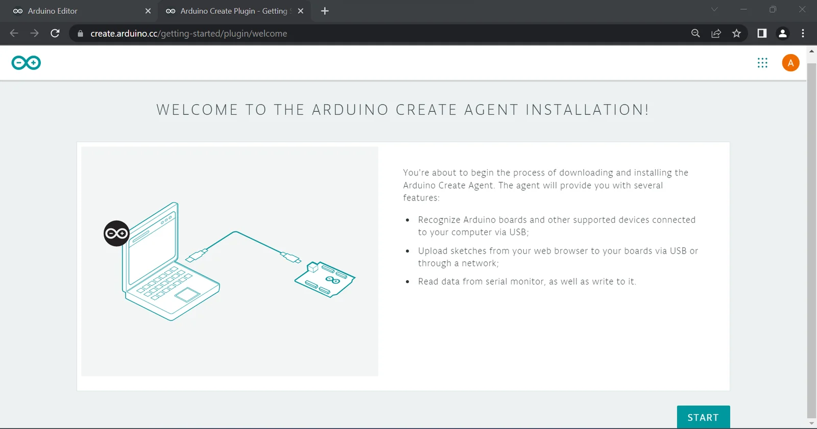
Click on the "Start" button to begin the process. The webpage first detects the Operating System and provides you with different versions to choose from based on this.
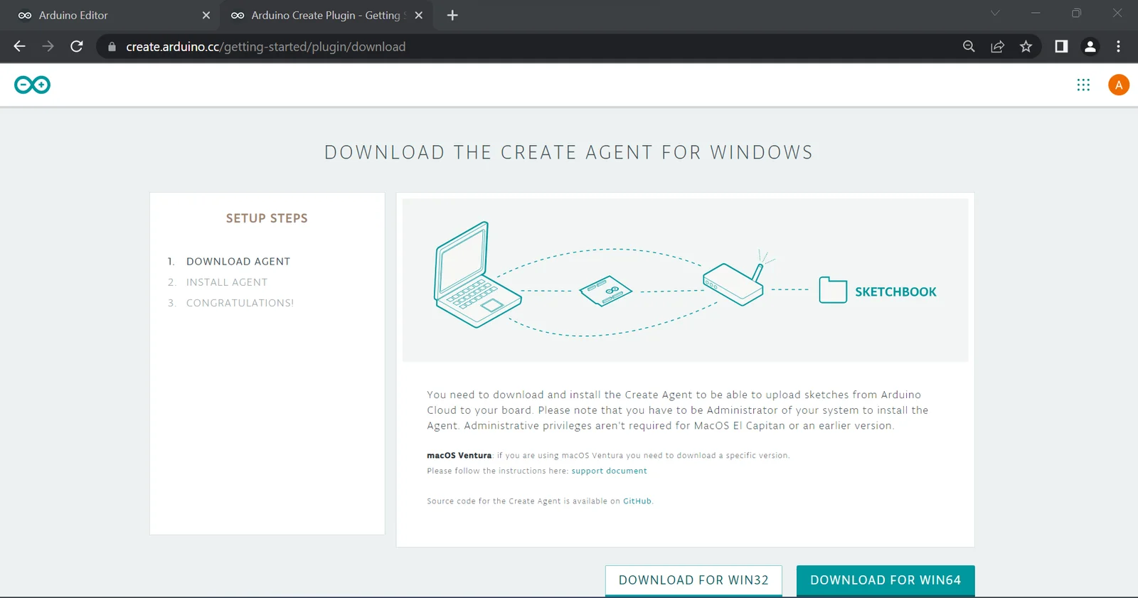
In the above case, we are on Windows and are presented with two options, i.e. WIN32 and WIN64. Since we are on 64-bit Windows (most users should be), the second option is selected. Make sure to choose the correct version from the options as per your operating system. This should start downloading the installer.
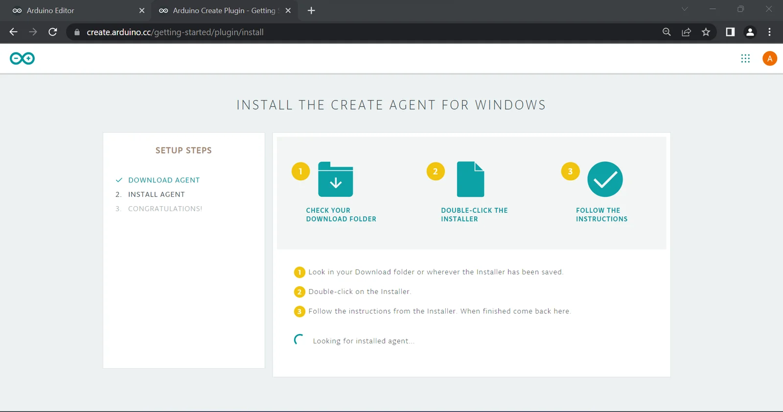
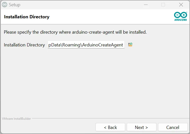
The first step is to supply the Installation directory, i.e. where the Create Agent executable and all related files will be stored. The default directories for different operating systems is shown below -
- Windows - C:\Users{username}\AppData\Roaming\ArduinoCreateAgent
- MacOS - Users/{username}/Applications/ArduinoCreateAgent
- Linux - /home/<User>/ArduinoCreateAgent
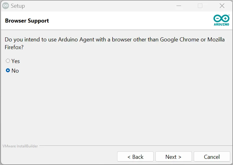
The installer then opens a prompt asking if the Create Agent will be used with browsers other than Google Chrome or Mozilla Firefox. Choose the correct option and go to the next step. In the above case, it is not intended to be used with any other browser.
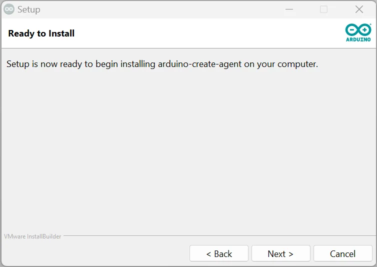
After the options have been set, the installer will inform you and prompt you to start the installation process. Click Next to continue. The installer will take care of the rest (Depending on the version being used, you may need Administrator privileges to install certain parts of the program).
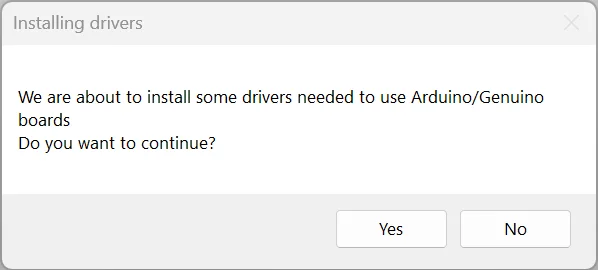
Separate prompts might pop-up for certain drivers, such as the one shown below. Click Yes to continue the installation.
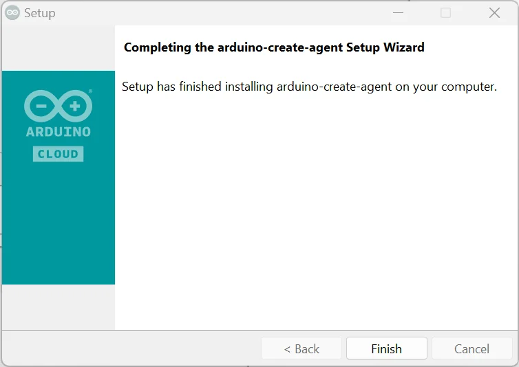
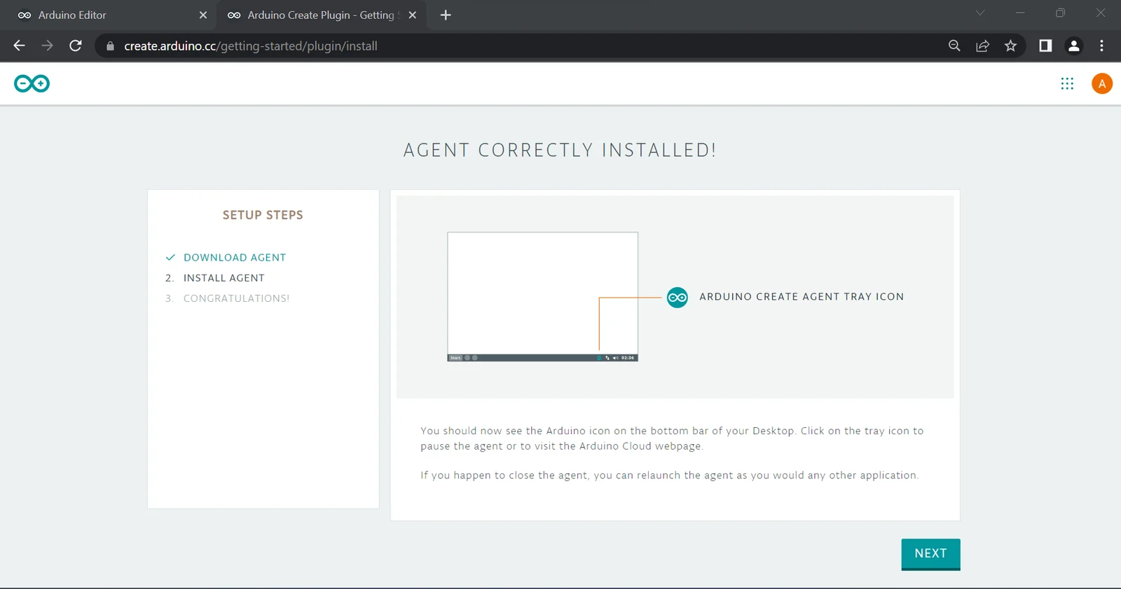
After the installation is complete, you can click the "Finish" button in the installer to close it. The webpage should have successfully detected the Create Agent as well. In case the webpage does not detect the Create Agent, try to reload it. If this still does not resolve the issue, manually search for the "Arduino Create Agent" program and run it. Reload the webpage once this is done to resolve the issue.
Blinky example on Arduino
In this section, we will build a circuit using the Arduino UNO, an LED and a resistor, and program it using the Web editor to blink the LED. We will understand the structure of an Arduino program and how it is used to control the hardware components connected to the microcontroller.
Required components
The components required to build the circuit are shown below -
- Arduino UNO and USB Type-B programming cable
- Resistor (220 Ohm or higher)
- LED
- Wires
- Breadboard (optional)
Steps to build the Blinky Circuit
The complete circuit can be built with or without a breadboard. Both are shown below -
The steps to build the above circuit are shown below -
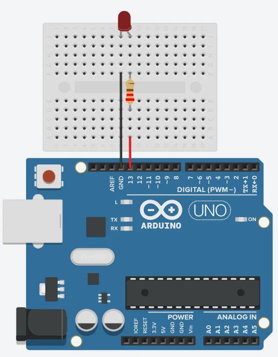
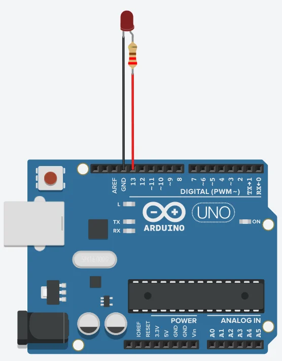
- The LED has two pins of unequal lengths. Connect one of the pins of the resistor to the longer pin of the LED (anode) and the other to pin 13 on the Arduino. We will use the program to toggle the voltage of this pin from 0v to 5v and back.
- Connect the shorter pin (cathode) of the LED to one of the available GND pins on the Arduino. Any pin labelled GND is at 0v and acts as a sink for current, just like the negative terminal of a cell/battery.
- Care should be taken to connect the LED in the right direction. Since LEDs are polarised components. they only allow current to flow in one direction (from anode to cathode).
- Likewise, the resistor between the LED and Arduino should not be neglected. LEDs (all diodes) are distinct from filament bulbs, and do not have a fixed resistance, i.e. their resistance decreases as the voltage across them increases. Consequently, a large amount of current can flow from the Arduino through the LED, similar to when a batter is shorted, thereupon burning the LED. The Arduino could also be damaged, since its pin are not meant to supply such large currents (> a few dozen milliamps).
Because the resistor is used to limit the current through the LED, it could have also been used between the Cathode of the LED and the GND pin. This would maintain the overall resistance of the path, and would therefore achieve the same effect.
Programming the UNO board using the Web editor
After the circuit has been built, we can write the program to blink the LED and upload it to the Arduino.
Writing the program
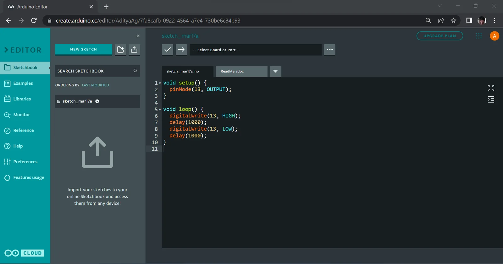
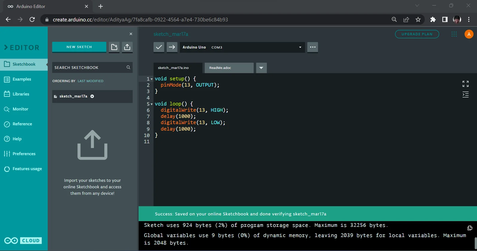
Open the Web Editor and go to the Sketchbook. It should contain the following code by default -
There may be some extra whitespace before or after the program, which can be ignored. Some lines may start with the // sequence, which indicates a single-line comment. These are pieces of text written by the programmer to explain the program, and are ignored by the IDE. Similarly, any text wrapped within /* */ is a multi-line comment. You may ignore these lines for now.
The setup function is a special function in the Arduino language. Code within this function is executed once at the start of the program. Hence, it is used for writing code that sets up hardware, variables etc. that are used by the application.
Similarly, the loop function too is a special function provided by Arduino. Code within this function is executed repeatedly ad infinitum (after the setup function finishes). Unlike programs written for your PC/mobile/laptop, programs written for microcontrollers are not normally meant to *finish* executing. Rather, they consist of an initialisation step, followed by an infinitely repeating task. This is reflected quite well in the setup-loop framework provided by Arduino.
To make the LED on pin 13 blink, paste the following code into the sketch file.
This is a fairly standard Arduino program, and it does several things. Let us look at its statements one by one -
We first use the pinMode function to set the mode of a pin. The first argument is the number of the pin that we want to affect (in our case, pin 13). The second argument is the mode we want to set the pin to. Since we want the pin to supply current/signals, we specify it to be in OUTPUT mode. OUTPUT is a case-sensitive constant in the Arduino Language. Since we only want to set the mode once, before we blink the LED, it is sufficient to put this in the setup function.
Next, we use the digitalWrite function to set the state of the pin. Similar to the pinMode function, the first argument is the number of the pin that we want to affect (once again, 13 in our case). The second argument is the logic level of the pin, which can be either HIGH or LOW. LOW indicates 0v, while HIGH indicates the logic level the Arduino board operates at. In the case of the Arduino UNO, this means 5v, but in some newer Arduino boards, this could also indicate 3.3v or less.
The function has been used twice, first to switch the LED on and once again to switch it off. Because we want to keep switching between the two states, it has been placed in the loop function.
While two uses of the digitalWrite function is enough to blink the LED, it would be executed millions of times per second by the Arduino. In effect, the human eye would observe the LED to be dimly lit, rather than blinking. To solve this, calls to the delay function are interleaved between the digitalWrite functions. The function accepts a single argument, i.e. the duration of the delay in milliseconds. A duration of 1000 has been used to create a delay 1 second.
Finally, the complete program should look as follows in the Web Editor -
Verifying and uploading the program
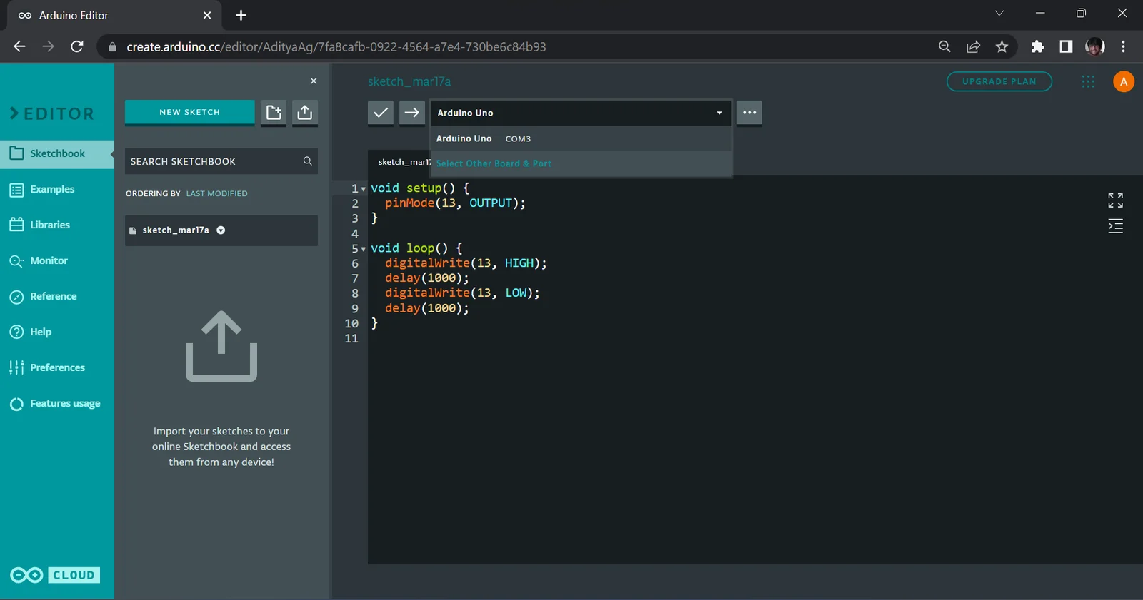
After finishing the program, we must compile and upload it to the Arduino. The first step is to connect your Arduino Board to your PC via the USB cable. While the Arduino is physically connected to your PC via USB, it is treated by the Operating System as a Serial device (older readers might be familiar with this protocol, as it was used extensively before USB to connect peripherals, such as modems, to desktop computers). On Windows, the name of the port should start with "COM", followed by the number of the port (such as COM1, COM2 etc.) while on Mac/Linux, it should show up under the /dev filesystem and start with "tty" followed by the number of the port (such as /dev/tty0, /dev/tty1 etc.) The allocation of the Serial Port happens automatically when you connect the Arduino, and you do not have to worry about this.
The action of plugging in the Arduino should automatically be detected by the Create Agent, and the dropdown above the editor should change to reflect this. Rather than asking for a board and port, it should show the board (Arduino UNO) along with the port it was assigned. In the case where this does not happen, you can manually select the port and board by clicking on the dropdown and selecting the correct entry.
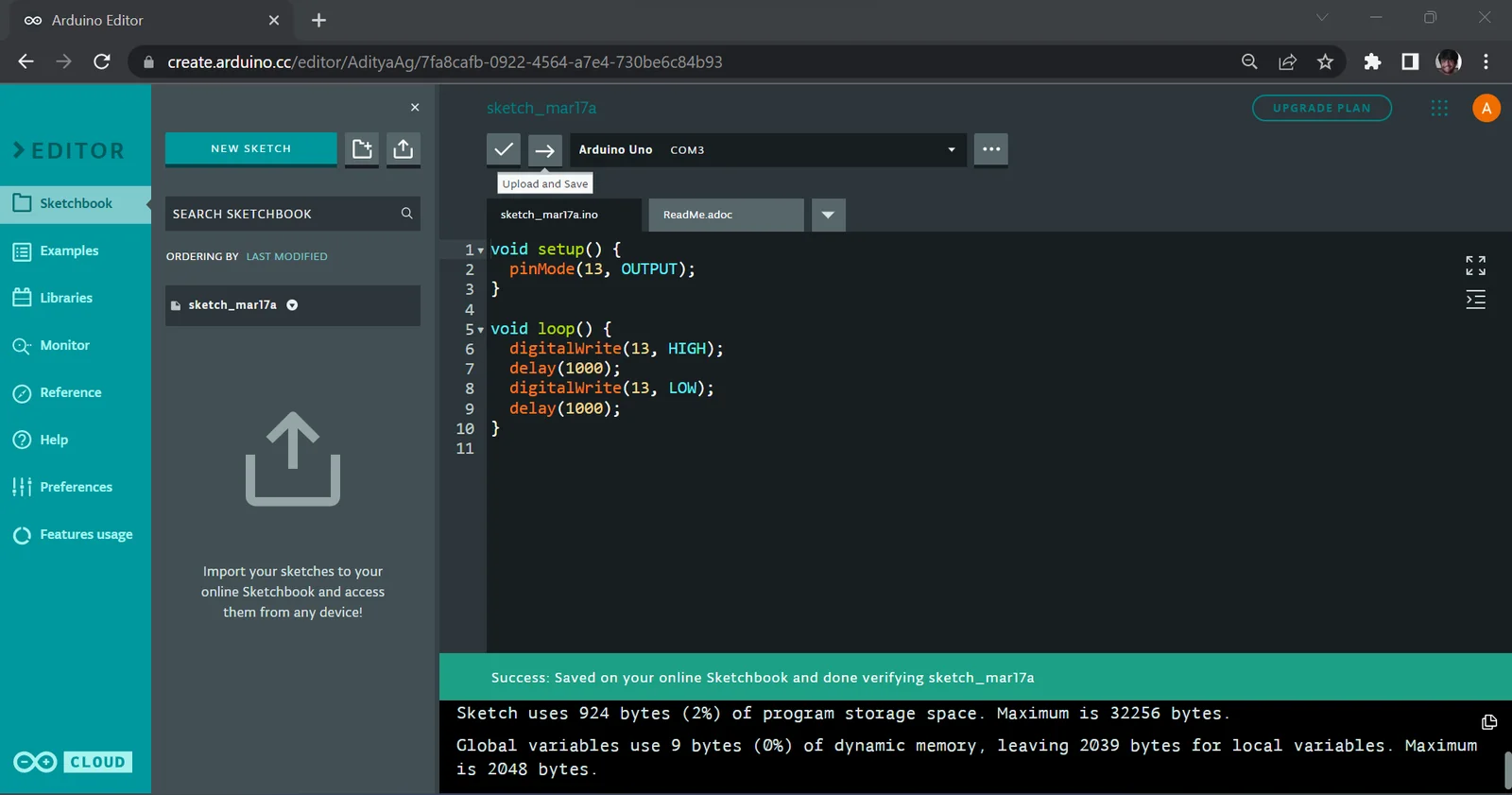
After selecting the board and port, click the verify button to save and compile the program. Any syntax errors in the program (such as missing semi-colons, missing/extra arguments to functions etc.) will be reported at this step.
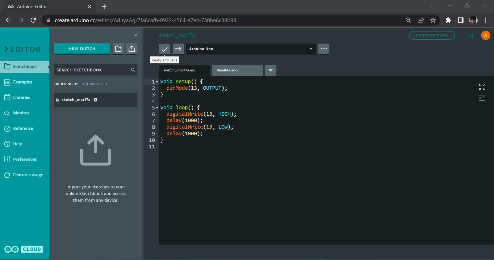
After verifying the program, click the Upload button the send the program to the Arduino.
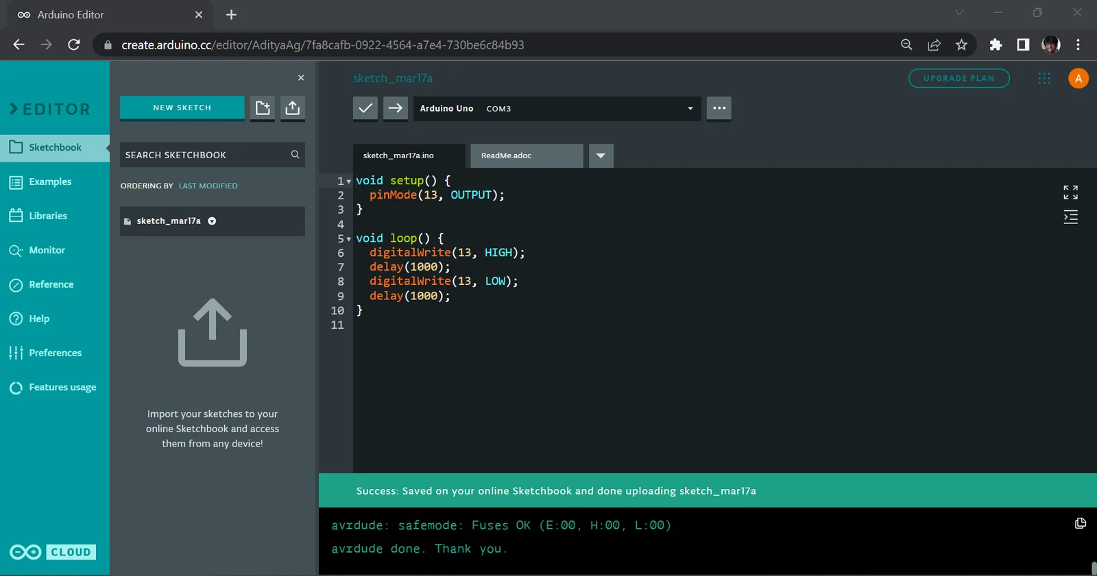
After the upload process is complete, the LED should start blinking, switching its state every second. Keen observers would have noticed that there is a small LED on the Arduino board, next to pin 13, which blinks synchronously with the external LED. This is an LED that is built into all Arduino UNO boards, and is connected to pin 13 using a resistor. Shown below is a diagram where this LED has been marked -
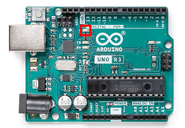
Most, if not all, Arduino Boards include a built-in LED on one of their pins. Because of this, the Arduino language includes a constant called LED_BUILTIN whose value is the number of the pin that has the built-in LED. The value of this constant is set when a board is selected from the dropdown. Shown below is the Blinkylinky program where the pin number has been replaced with the LED_BUILTIN constant -
The code shown above is considered superior because of improved readability and portability. Because the pin is referred to by a name rather than a number, the reader can quickly determine what the intent of the programmer is. Additionally, the same program could be used with other Arduino boards without modification, as the value of the constant is automatically changed by the IDE.
After compiling and uploading this program to the board, you can observe that it produces the same result as before, i.e. the LED is toggled every second.
Fading an LED with Arduino
In the previous section, we blinked an LED with the Arduino. In this section, we will fade the LED, i.e. change its brightness smoothly from a completely off state to an on state. Once again, we will build the circuit with the Arduino UNO, an LED and a resistor and program it using the Web Editor.
Required components
The components required to build the circuit are the same as the previous circuit and are shown below -
- Arduino UNO and USB Type-B programming cable
- Resistor (220 Ohm or higher)
- LED
- Wires
- Breadboard (optional)
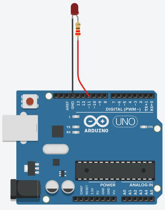
Building the Circuit
The circuit is similar to the one used for Blinky, with the only difference being the pin used to drive the LED. Two versions of the circuit are shown below, with and without a breadboard -
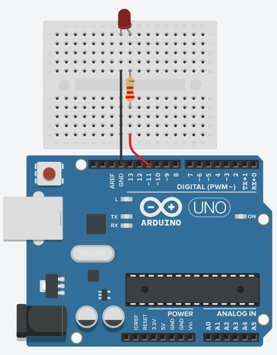
The steps to build the above circuit are shown below -
- Connect one of the pins of the resistor to the longer pin of the LED (anode) and the other to pin 11 on the Arduino. Pin 11 should have a tilde (~) symbol before its number. This indicates that the pin is capable of analog output.
- Connect the shorter pin (cathode) of the LED to one of the available GND pins on the Arduino.
The precautions that were taken while building the Blinky circuit are applicable for this circuit as well.
Programming the UNO board using the Web editor
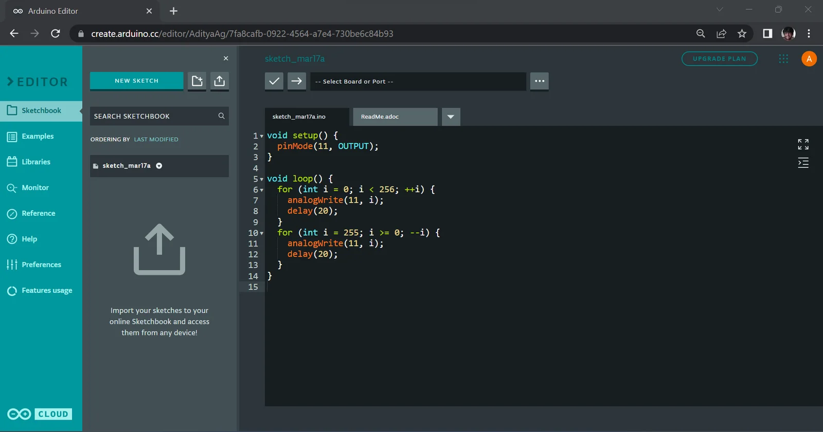
Create a new sketch in the Web Editor and paste the following code into it -
Let us look at what it does, step-by-step.
We first use the pinMode function to set pin 11 to be an output pin. We have used pin 11 because it is one of the few digital pins capable of analog output. A digital pin is capable of analog output if it's number is prefixed with the tilde (~) symbol.
Next, we use a for loop to count from 0 to 256 (excluding the right boundary). Every iteration of the loop, the variable i is incremented by one. We then use the analogWrite function to write this value to the pin. The analogWrite function is given two arguments (similar to its digital counterpart), the first being the pin to affect and the second being the value to write. The analog output has 8-bit resolution, a value of 0 indicates 0v, and 255 indicates 5v. To convert the desired voltage into a number for analogWrite, the following formula can be used -
result = v * 255/5The voltage is slowly increased from 0v to 5v. Short delays of 20 milliseconds have been added at the end of loop iterations to show the dimming effect clearly.
The second loop is the same as the first loop, except that the counting is reversed (from 255 to 0). This slowly decreases the voltage from 5v to 0v.
The sketch should look as follows in the Web Editor -
You can verify and upload the program to the Arduino in a similar fashion to the previous example. After this is done, the brightness of the LED should slowly increase from a completely switched off state to a completely switched on state and back, with an entire cycle taking a little over 5 seconds.
This is a good time to mention that the Arduino is not capable of true "analog output" on its own, i.e. the analogWrite function does not write a true analog voltage to the pin that we specify, but rather simulates an analog output using a technique called Pulse Width Modulation (PWM), wherein the state of the pin is switched between 0v and 5v very fast (> hundreds of times per second) to give the illusion of an intermediate voltage being present. The ratio between the time spent in an "on state" and "off state" is what determines the apparent voltage of the pin. For a dedicated tutorial on PWM using Arduino, click here.
Using a button to control an LED
In this section, we will see how to use a pushbutton to toggle an LED with the Arduino UNO. As noted before, a pushbutton is momentary, i.e. it only closes the circuit as long as it is held-down. With this in mind, we will use the Arduino to toggle the state of the LED after every button press.
Required components
- Arduino UNO and USB Type-B programming cable
- Resistor (220 Ohm or higher)
- LED
- Pushbutton
- Wires
- Breadboard
Building the Circuit
The circuit is the same as the Blinky circuit, albeit with the addition of a button on pin 2. It should look as follows when built on a breadboard -
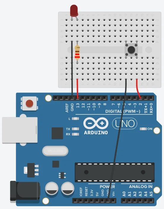
The steps to build the circuit are shown below -
- Connect one of the pins of the resistor to the longer pin of the LED (anode) and the other to pin 13 on the Arduino.
- Connect the shorter pin (cathode) of the LED to one of the available GND pins on the Arduino.
- The pushbutton has 4 pins, and actually acts as a two disjoint buttons. Each pair of parallel contacts are connected when the button is held down. This type of button is called a double-pole button, where a single mechanism controls the connection between two pairs of contacts. Choose one of the pairs and connect one of its ends to pin 2 and the other one to a GND pin, as illustrated in the above diagram.
The button has been connected to GND instead of 5v, to take advantage of the built-in pullup resistors in the Arduino. If the button were instead connected to 5v, we would have to use external pulldown resistors to make sure that the pin does not remain floating. If you are not familiar with pulldown/pullup resistors, they are used to make sure that the input pin on a microcontroller are do not remain in an indeterminate state when not connected to
When the button is held down, the digital pin will read a low-state, and when it is released, it will read a high-state. Note that this is the reverse of what might normally be expected, i.e. a low-state when released and a high-state while being held down. If you are not familiar with pullup resistors, click here.
Programming the UNO board using the Web editor
Create a new sketch in the Web Editor and paste the following code into it -
Let us look at it step by step -
The first step is to create a variable that stores the state of the LED, with its initial value being LOW. Because the value of the variable must persist across calls to the loop function. Whenever we detect the button being pressed, we invert the value of this variable and write it to the pin using the digitalWrite function.
We first use the pinMode function to set pin 13 to be an output pin (pin 13 has been referred as LED_BUILTIN) and pin 2 to be an input, and enable the internal pullup resistor.
Finally, we keep checking whether the pin has been pulled low or not. When this occurs, we toggle the value of the ledState variable and we write it to the led.
The delay has been added to the end to solve the issue of bouncing. Bouncing is an issue caused in pushbuttons when the metal contacts bounce several times when the button is pressed/released before being firmly connected/disconnected. While this happens too fast for humans to notice, the Arduino reads this as multiple presses and toggles the LED several times. Adding the delay makes the program ignore clicks that happen within 200 milliseconds of a press, which is plenty for most pushbuttons.
After the program is verified and uploaded to the Arduino, the LED should start in a switched-off state. Pressing the button and releasing it once should switch it on, and pressing and releasing it once more should switch it off again. You can try to experiment with changing the bounce delay to see how this affects the LED.
Closing Thoughts
In conclusion, getting started with electronics and programming is easier than ever thanks to Arduino. Whenever you choose to work with Arduino, you have a wealth of resources and tools available online, and a passionate community of like minded people, all working together to learn more and grow. By following the steps outlined in this guide blog, you should be equipped to unlock the power of Arduino and start building your own electronics creations in no time. Happy hacking!
Moving on from where, you can start working on simple DIY project ideas, such as a light sensing bulb, motion triggered alarm, and gradually move onto advanced applications requiring connectivity, movement etc such as a remotely operated garden watering systems, robots etc. With Arduino, your imagination is the only limit. Happy tinkering!