Arduino Tutorial: Touch and capacitive sensing
By Aditya
/
June 19, 2019
In this tutorial, I will show how to use an Arduino for touch and capacitive sensing. Not just touch, but to detect the force exerted and the distance from the finger too. I will briefly explain the theory and then build a touch sensitive circuit with a simple wire, resistor and LED along with the Arduino. Let's get started!
What is capacitive touch sensing?
The smart phone revolution has deeply influenced our daily lives with touch based interactions. You tap and press and slide and swipe (and a whole lot more!) at specific places on the touch screen, and the phone detects this and alters the contents of the display depending on your gesture. However, if the same gestures were performed instead using a pencil or a pen, the device would reject them.
While your finger is detected, other inanimate objects are not. How is this made possible?
How does it work?
Before I explain how this is being done, try to cover a pencil with foil and use it as a stylus (while touching the foil). While the bare pencil was ignored by the screen, the foil is detected.
Clearly, there are no buttons begin used, since they can only detect pressing and releasing, not pressure or distance. They also contain moving parts, which means the display must be able to move as well, and might break it. Buttons also can't differentiate between your finger and the pencil.
This is where capacitive sensing comes into the picture, where all you need is a conducting surface and a microcontroller (an Arduino or equivalent works fine). The conducting body (represented using a brown circle) is connected to two pins on the microcontroller.
Initially, current is supplied to pin 1, and simultaneously a timer is started. The current must flow from pin 1 to the conductor, throughout the conductor, and then to pin 2, at which moment the timer is stopped. Remember that the electrons must travel throughout the surface of the conductor and can't directly travel from one of its ends to the other.
Now, when we bring our finger or any large conducting surface (represented by the red rectangle) near it, something happens.
A capacitor gets formed between your body (acts as first plate) and the conductor (acts as second plate). Because of this, the current takes either longer or briefer to flow through the conductor, and the value shown by the timer changes. This change is used to detect touch, pressure and distance
A pencil is made of wood/plastic and cannot form a capacitor. Its graphite lead (although a conductor) is too small to cause observable changes. The foil works when you are touching it because it merely "extends" your finger, but otherwise does not work for the same reason as the pencil's lead.
In case you were wondering, this does not shock you because the current flowing is very low and dry skin is not a good conductor. In fact, it is not your finger which is making the capacitor, but the water and salts under your skin that do this.
Now that you have understood the theory behind cap sense, it's time to build a project using the Arduino.
Step 1: Getting the parts
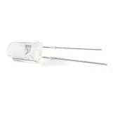
To complete this project, you will need four components, an Arduino or equivalant (I will be using an Arduino UNO), a piece of foil/metallic surface/wire, an LED and a resistor whose value is anywhere between100 kilo ohms and 1 mega ohm (for this project, the higher the resistance the better). The color code for a 1 mega ohm resistor is brown-black-green. I will link a resistor color code calculator at the end of this tutorial.
The purchase links for the parts are given at the end of this tutorial. If you are not familiar with arduino or its programming, then you can read my tutorial on getting started with Arduino. In the next steps, we will first make a simple circuit that can only detect the presence of a touch, and then make some changes in the code so as to be able to detect the proximity of a human.
Step 2a: Making the touch detection circuit
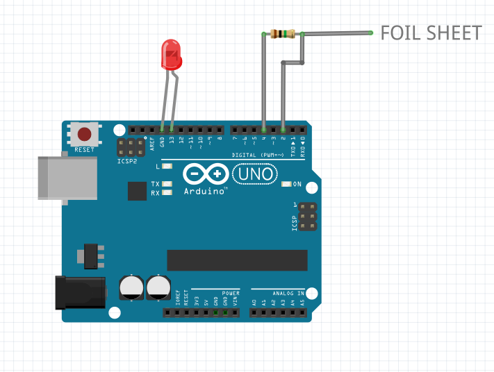
To start, take your wire and strip it down completely (remove all of the insulation) and connect it to pin 2 of the Arduino. Then connect its end to the resistor which is in turn connected to pin 4. If you have a piece of foil, connect it to pin 4 as well. If you have the LED, connect it to pin 13, although most Arduino boards and clones have built in LEDs which can also be used. That's it, your circuit is complete! Here is how it might look-
Step 2b: Writing the code for capacitive touch
In this step, we will be writing the necessary code for detecting touch and see how it works.
Start by defining two pins as input and output of the sensor. In this case, I have used 4 as OUT and 2 as IN. Like this-
Then, start the Serial monitor and also set the pin modes for OUT, IN and LED_BUILTIN. OUT and LED_BUILTIN are output and IN is input. It should look a bit like this-
Now that the initialization is complete, it is time to get to the main part, the loop.
First, set OUT to low and then delay by 10 milliseconds. This makes sure that there is no noise in the sensor before we take the reading and also limit the speed at which the data will be printed on the Serial monitor (Later on, the delay can even be reduced to 1 millisecond). Then create a long integer variable called startTime and set it to micros(). This is how it should look-
Now, set OUT to high and start a while loop which should run until INno longer detects a low signal. After the while loop has stopped, create another variable called sensVal and set it to the difference between micros() and startTime. Finally, print it on the Serial monitor. This is how the entire code should look.
That's it, you're done! Let's understand the exact meaning of the code before running it. The output pin is first set to low, so as to prevent any electrical noise present in the circuit from affecting the reading. After this, we create a variable which will hold the start time of the current read. micros() gives the number of microseconds which have passed since the Arduino started running the current program/sketch.
The, OUT is set to high and immediately a while loop is started whose function is to simply stop the program when IN receives the signal. As soon as it does, we find the amount of time which has elapsed since starting the read (by subtracting current time from startTime). This value changes depending upon the objects kept near the foil and resistor.
Now, select the correct board and port, compile your sketch and hit upload! If everything goes right, then the moment you bring your finger or palm close to the sensor, the value of sensVal should start to go up.
But wait, you say, what about the LED? It is going to be used to indicate the presence of a touch. But to do that, we first need to define what a touch is.
Let's see what I mean by this.
Step 2c: Tuning the touch sensor
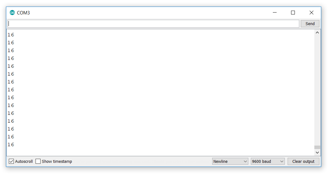
You need to get the approximate values of the sensor when the sensorIS being touched and when it IS NOT being touched, and log them. For me, they were 16 and 196, but they may be completely different values for you, depending on your humidity, altitude, temperature etc. Then you need to average these and store them in a variable called touchVal.

This value acts as a threshold to determine if the sensor is being touched or not. Simply modify the code to set the LED on if the value of sensVal goes above touchVal and set it off when it goes below it. This is shown below-
Step 3a: Distance and proximity
Now that you have successfully detected whether a touch is present or not, it is time to do something interesting!
Let's make a directionless human proximity sensor. It will be similar to the touch sensor, except instead of merely switching the LED on and off, its brightness will change depending on how close or far away you are from the Arduino, no matter what direction it is.
The circuit remains the same with only one change- connect the LED to a PWM capable pin on the Arduino rather than pin 13. I have used pin 11, but you can use any other pin whose number is prefixed with the ~ mark. For a detailed tutorial on using PWM with the Arduino, click here.
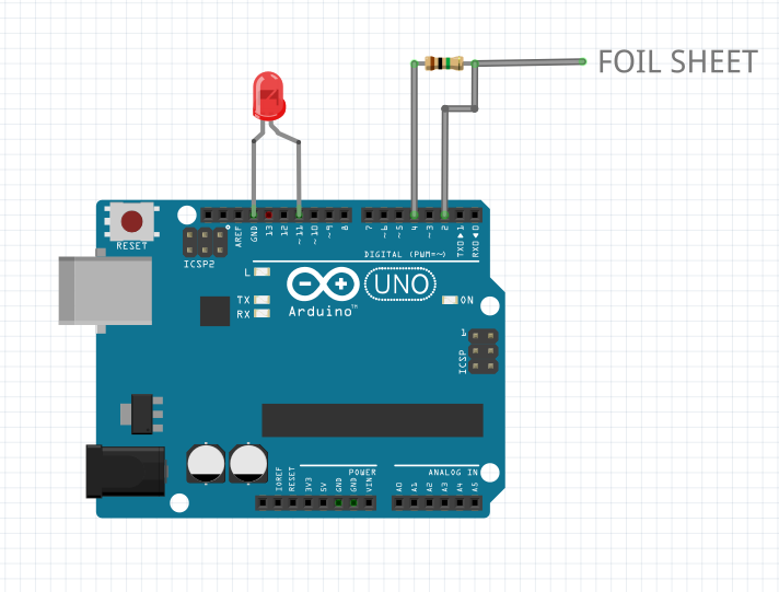
Yet another thing to keep in mind, is that this circuit absolutely needs the foil sheet/metal plate to function, as proximity detection requires the area of the conductive surface to be quite large. If you do not have this, you can even stick the wire into a bowl of salty water or into a fruit (don't worry, the fruit will still be edible after the project is complete.)
Step 3b: Code for proximity detection
We can re-use the previous code for this project, so start by copying and pasting the previous code for simple capacitive sensing. We will make changes to this code instead of writing everything from the the ground up.
The first change you must make is to remove the if-statements in the end which turn the led on and off and then replace LED_BUILTIN with the PWM pin you have used for connecting the LED. In my case, I used 11.
Next, remove touchVal and instead create two variables called maximum and minimum and give them the maximum and minimum values your sensor received. If you just attached the piece of foil, then I would recommend that you retake the values (I did this and got different values).
Finally in the end, you need to add a special bit of code after which your program should look like this-
This tells the program to map the value of sensVal, from its minimum (no touch) to maximum (touch) to the range of the LED and then set the brightness of the LED appropriately.
After compiling and uploading, you will see that the LED becomes brighter as you bring your palm closer to it and gets dimmer as you go away from it. And you're done!
Playing around with the values
Now that we are done with the projects, you can try to make changes and play around with the code and circuit. For starters, try changing the value of the resistor you are using and how it affects the sensitivity and range of the sensor. Try changing the size of the foil you are using and seeing what effects it has.
Capacitive sensing is an extremely fun and useful way to detect touch and has many practical applications as well. What will you do with it? Leave a comment down below.