Using buzzers with Arduino
By Aditya
/
April 1, 2019
Buzzers can be fun to use, and very useful too! In this blog, I will be showing how to use an Arduino along with a piezo buzzer to make sound, play different notes (using the tone function) and more. This knowledge can be used in a whole lot of projects, including alarm clocks, playing songs etc. Lets get started!
What is a buzzer?
Before we use a buzzer, it is necessary to understand what it is. A buzzer (also called a beeper), is a simple device which produces sound when an electrical signal is passed to it. They can be based on many different technologies, however, due to their lower costs, piezoelectric buzzers are the most commonly found ones nowadays. As a result I will be using them in this blog.
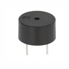
What is inside a piezo buzzer?
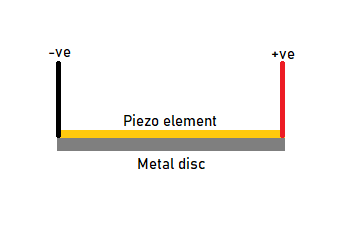
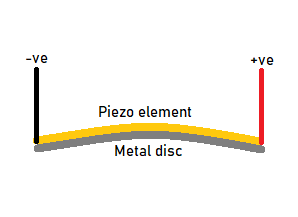
A piezoelectric buzzer (or simply, piezo buzzer) consists of a thin metal plate with a flat piezoelectric element (often disc-shaped) on top of it. When a voltage is applied to the ends of the piezo element, it deforms a set amount along with the metal plate, producing a sound. Depending on the magnitude of the applied voltage, the sound might be louder or fainter. Switching the voltage at different frequencies will cause sounds of different frequencies to be produced.
Different types of piezo buzzers (active & passive)
While all piezo buzzers are based on the same principle, not all of them are the same. Piezo buzzers are divided into 2 categories, namely active & passive.
Passive buzzers are regular piezo buzzers which only contain the bare minimum hardware (mentioned above) and need to be provided with an audio signal to generate a sound. Simply "switching them on" will do nothing more than produce a click sound. This is because simply applying a voltage to them will change the shape once (producing a single "click") and not have any change after that.
Active buzzers, on the other hand, contain the some extra components along with the usual. They contain an internal oscillator circuit which automatically generates an audio signal (of constant frequency) when power is supplied to them. As a result of this, they don't need any extra control hardware or signals and simply supplying power to them will cause them to produce sound.
They can usually only produce a sound of a constant frequency, however if supplied with an audio signal of varying frequency, then the resultant sound's wave can be defined to be the product of the internal and external waves.
R(t) = E(t) * O(t)
Where R describes the resultant wave, E describes the external signal and O describes the internal oscillator's signal. This means that even though it is possible to play sounds of different frequencies on them, the result is usually not very nice sounding and definitely not recommended.

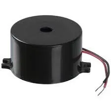
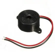
As you can see from the above images, they usually look the same and there is no hard and fast rule to differentiate between the two simply by looking at them. Therefore, it is advisable to make sure about the type of buzzer while buying it.
Now that we have the theory out of our way, it is time to start working on a simple project.
Step 1: List of components
In this step, I will be showing you the various components required.
- Piezo Buzzer (preferably passive, however active will work as well)
- Arduino UNO (or similar microcontroller)
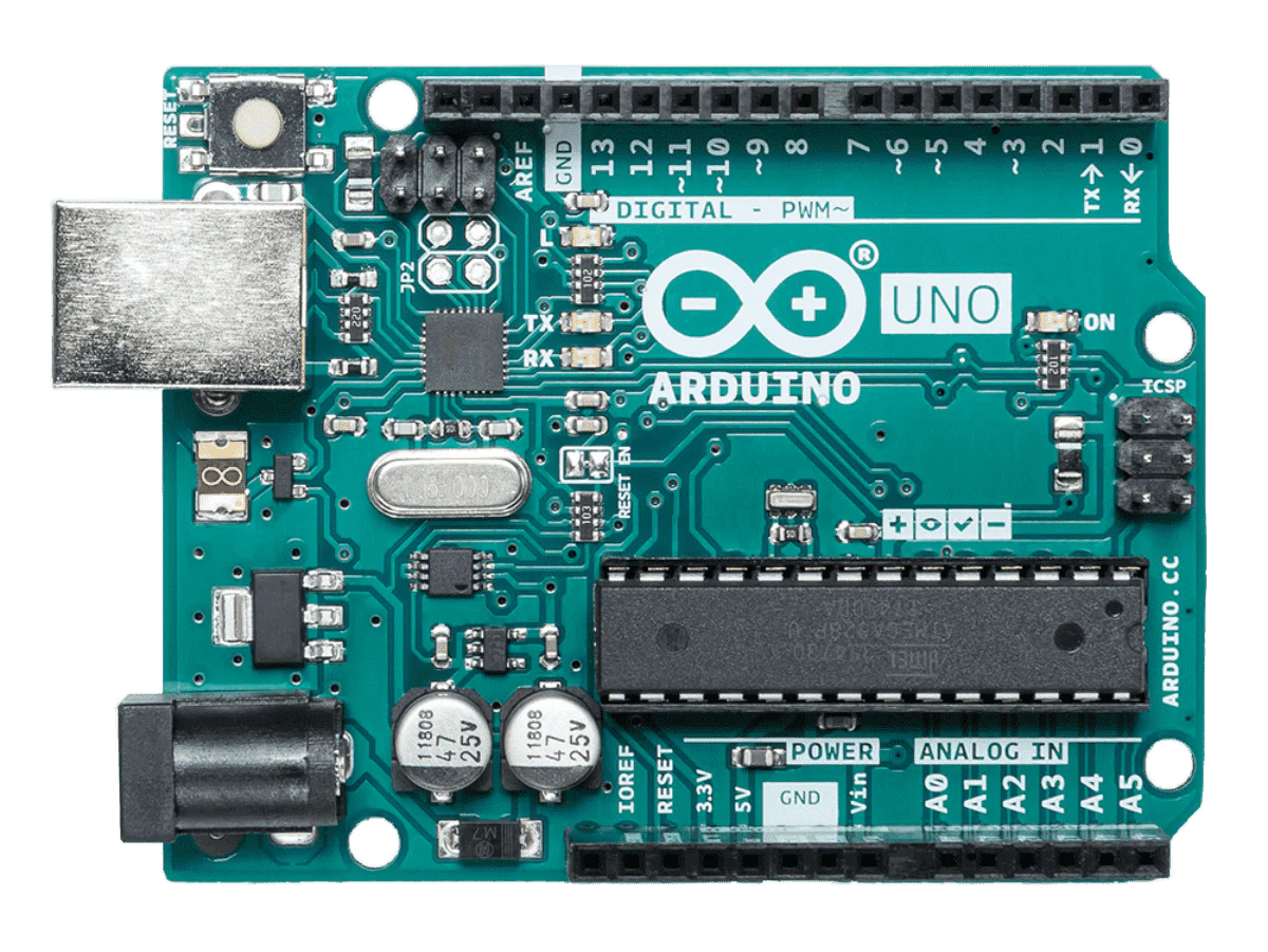
Arduino UNO - Battery (optional, as you can use this to power your project from outside your computer once it is complete, ensure that the battery can provide over 7.5v)

9v Battery
Step 2: Connecting the buzzer to the arduino
In this, step, we will connect the buzzer to the Arduino. Start by identifying the positive and negative pins on the buzzer. Most passive buzzers (and all active buzzers) will be polarized, i.e. they can only be connected to power one way and not the other.

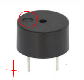
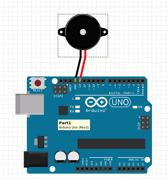
You should be able to identify the positive and negative pins from the above image. All that is left now is to connect it to the Arduino. The negative pin from the buzzer can be connected to any of the available GND (Ground) pins while the positive pin can be connected to any of the digital output pins (from 0 to 13). For this tutorial, I am connecting it to pin 13. Here is an image of how this will look-
Step 3: Writing code to make the buzzer beep
In this step, we will be writing the code that controls our buzzer. To start, we will just switch it on and off every half a second. If you are not familiar with Arduino programming, click here to learn how to get started with Arduino.
Let's understand this code line by line. In the first line, I create a variable buzzpin and give it a value of 13. This is the pin which controls the buzzer, make sure you assign it the same value as the pin your buzzer is connected to.
I then set the pin to output by saying pinMode(buzzpin, OUTPUT) and then change its state over and over again from on to off and back every half a second. You can upload this to the board and play with the delay a bit to get different beeps. If your buzzer does not work then make sure your code is alright and it is firmly connected the the board.
If the problem persists then try replacing the buzzer with an LED (keeping the polarity right) and if the led works, then you can know for certain that fault is in your buzzer and not the circuit or code.
Now that we have learned how to switch the buzzer on and off, let's play musical notes!
Step 4: Tone function to play musical notes
Before we play musical notes, let us quickly understand what they are. Musical notes are simply sounds of specific frequencies. When played in the right order and for the right duration (by an experienced musician) they can create music. In an Arduino, this can be done using the tone function.
This might be sounding a lot like PWM to some of you, however it is not so. In Pulse Width modulation, the frequency is kept constant while the duty cycle (ratio of on-time to off-time) of the wave is changed. In tone, however, the duty cycle is kept constant (50%) while the frequency is changed.
The tone function has 3 parameters (which you might have already realized). We first tell it which pin is being used. In this case we are using buzzPin. We then tell it the frequency we need to play in Hertz (The minimum frequency accepted by the tone function is 31 Hz). and then finally for how long(in milliseconds). That's it!
Also, do keep in mind that while using tone, you can not use PWM on pins 3 and 11 on the UNO due to both using the same internal timer. Trying to do so will give undefined behaviour.
Final Remarks
Hope it helps you play around with Buzzers and have fun!
Feel free to leave your comments/thoughts.