Using an SD Card to store and display bitmap images on a 3.5 inch TFT LCD Display and Arduino (Part 4 of 6)
By Aditya
/
July 7, 2024
This blog is shows how to use an SD Card with a 3.5 inch TFT LCD Shield (driven by an ILI9486 driver) and an Arduino UNO R3/R4/Mega for beginners. It is the fourth of six parts, and shows how to get started with the SD Card to load and display images on the TFT LCD. It contains two sections. The first sections shows how to prepare the SD Card for use with the library and introduces the SD Card library. The second section shows how to read image files from the SD Card and show them on the 3.5 inch TFT LCD module. The procedure to use text files was shown in the previous blog.
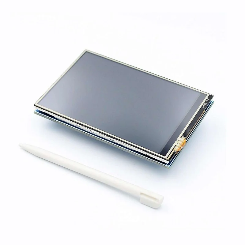
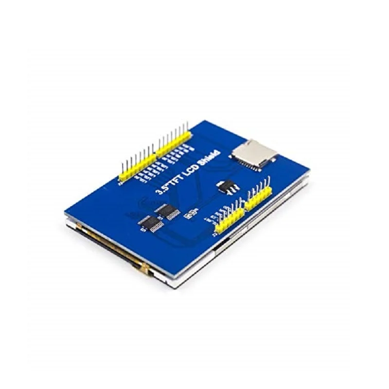
The ILI9486 TFT LCD shield has a thin film transistor (TFT) liquid crystal display (LCD) with a generous resolution of 480x320 pixels & 16-bit color depth (65,536 unique colors), a builtin touchscreen, and abuiltin SD Card slot. It is sold under different names, a popular one being ILI9486 MCUFRIEND TFT LCD Shield, and its form factor and low-cost make it a very attractive option to add rich display capabilities to your Arduino projects.
This is a comprehensive series of six blogs about interfacing a 3.5 inch TFT LCD Shield with an Arduino Board (including the newer UNO R4 Minima/WiFi). For an introduction to the display and the libraries, refer to the first part of this series. To see how to calibrate and use the touch screen, refer to the second part of this series. To see how to use text files with the library, refer to the third part of this series. The fifth and sixth parts of this series shows how to use the TFT LCD Shield to create a Paint app (including a color picker, size picker and canvas) and the popular Tic-Tac-Toe game.
All the examples given in this blog (and series) have been tested on the Arduino UNO R3, Arduino Mega, Arduino UNO R4 Minima and Arduino UNO R4 Maxima. This blog uses the Adafruit GFX, Adafruit Touchscreen and MCUFRIEND libraries for performing various tasks with the displays, and the SPI library and SD Card Library to communicate with the SD Card.
Let's get started!
Briefly recapping the previous parts
The first part of this series went over the hardware components of the ILI9486 LCD Shield, and showed the libraries required to operate it (along with their installation). It also covered the software architecture used to drive the display and ran some builtin examples as well as our own programs to verify its working.
The second part picked up from here and comprehensively talked about and demonstrated the calibration of the ILI9486 TFT LCD's touchscreen (along with a program and video).
The third part moved the focus to the SD Card slot on the TFT LCD Shield and showed how to load/store text files, using both builtin examples and our own examples focusing on practical use cases.
This blog shows how to use the builtin SD Card slot on the Shield to store image (bitmap) files to draw on the display. It also shows how to store bitmaps in the Arduino's flash and draw them on the display.
Preparing the SD Card and introducing the Library
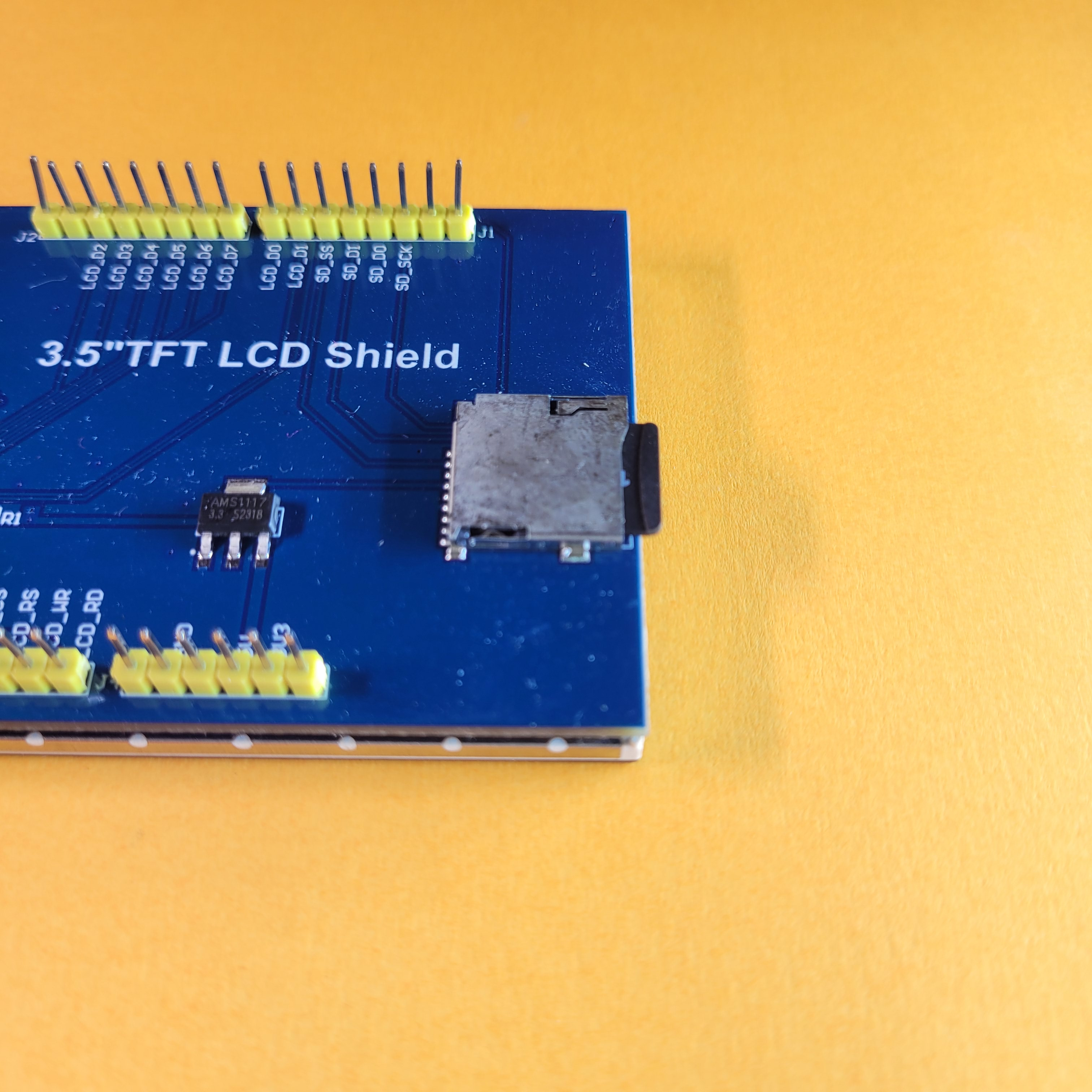
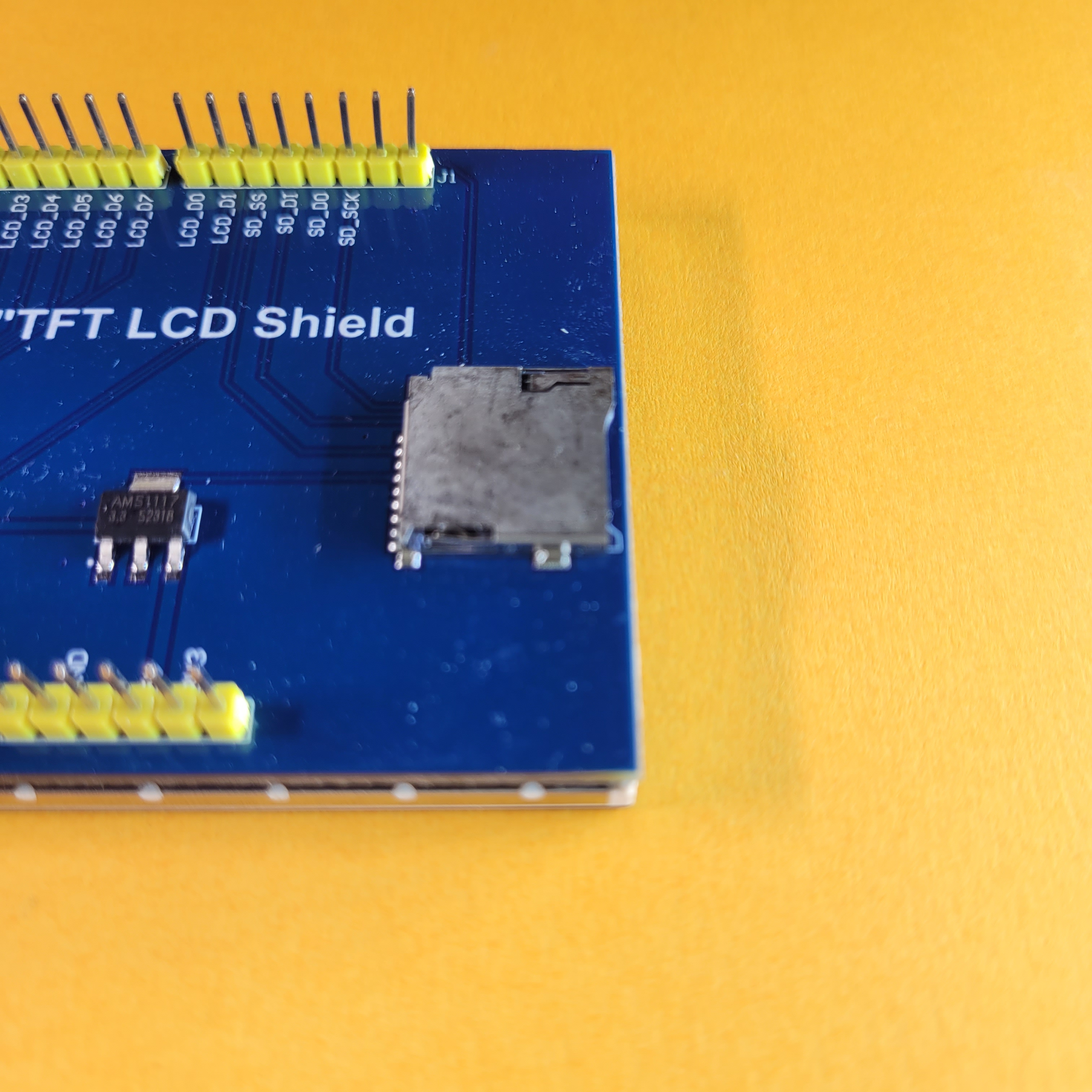
This section shows how to prepare the SD Card for use with the ILI9486 TFT LCD Shield, and introduces the library used to communicate with the SD Card on the TFT LCD Shield. Recall that the Shield has a builtin SD Card slot, which we can use to add persistent storage to the Arduino. Note that the information below is repeated in the previous (third) part as well, and these two blogs can be read independently. If you have read the previous part, you can skip this section entirely.
Formatting the SD Card
The SD Card should be formatted with a FAT16 or FAT32 filesystem, with a single partition only. This is a mandatory step to perform, without necessarily getting into the technical details of formatting. Briefly, formatting refers to the process of configuring a storage medium so that it can be read-from/written-to by controllers (such as your PC or the Arduino). This involves "laying-out" a filesystem on the medium and partitioning it. You can read more about the history of formatting here.
There are a vast number of tutorials online that already explain how to do this, but a brief summary of the steps are shown below for different operating systems. Irrespective of your operating system, you will need an SD Card slot on your Laptop/PC/Mac, or an external SD Card reader if one is not available.
Formatting on Windows
Open the file manager program and navigate to the newly connected drive (this is how Windows should present the SD Card once its plugged-in). The formatting process clears all the data in the SD card, so make sure to select the correct one (especially if multiple devices are connected).
Right-click on the drive and select the format option. Make sure that there is only one partition and other information (such as capacity) are correct. For the file-system option, select the FAT filesystem. After this, click start to begin the process.
Once completed, the card is ready to use.
Formatting on Linux (Ubuntu)
Open the Files program (Nautilus), and right-click on the drive that appears. From the drop-down, select the format option to open the formatting wizard. Close the Files window and select the option labelled FAT. You can optionally provide a name for the drive as well. After this, click next and follow the steps to finish the formatting process.
Once completed, the card is ready to use.
Formatting on Mac
Open the Disk Utility program and select the SD card from the left pane. The formatting process clears all the data in the drive, so make sure to select the correct one (especially if multiple devices are connected).
Click on the Erase option and select FAT in the options that come up. Finally, click Erase to begin the process.
Once completed, the card is ready to use.
Understanding the usage of the SD Library and pin connections
The library used to communicate with the SD Card is the SD Library that is included with the Arduino IDE by default. On PlatformIO, this can be included by adding arduino-libraries/SD to the lib_deps section. The following snippet shows the basic usage of the SD Library -
Note that the SPI library is included before the SD Library. This library is also included with the Arduino IDE by default.
First, the SD object is initialized in the setup function using thebegin method. It accepts a single argument - the chip-select pin of the SD Card (in case of the ILI9486 LCD Shield, this is pin 10). The method returns true if the initialization was successful and false otherwise. This should be checked before using the SD object further.
Next, the exists method is used on the SD object to check if a file exists. It accepts a single argument - the name of the file (as a string) to find. It returns true if the file exists and false otherwise.
After this, the open method is used on the SD object to open a file for reading. It accepts two arguments, which are the name of the file (as a string) and the mode to open it in. The latter can be either FILE_READ (allows reading only; does not create the file if it does not exist) or FILE_WRITE (allows reading and writing; creates the file if it does not exist). The method returns a file handle of type File, which refers to the opened file.
In an if-statement, the handle evaluates to true if the file was successfully opened and false otherwise. This should be checked before performing further operations on it. Note that the FILE_WRITE mode opens the file in append mode if it already exists, i.e. existing data is not cleared when the file is written to.
Files on the SD Card can be treated as a sequential array of bytes. Each file has a size, which corresponds to the number of bytes in the array. The file handle keeps track of this as well as the location of the current character being processed.
This way, the file handle can be used in a manner similar to the Serial object. Methods such as write, print and println can be used to write to the file. Whenever a character is written to the file, it is placed at the current location and the location is incremented (this happens automatically). To manually get and set the current location, the position and seek methods can be used.
To read from the file, the read and peek methods can be used. Theread method returns the character at the current location and automatically increments the location, while the peek method returns the character without incrementing the location. To check if the file has any characters left to read, the available method can be used.
After using the file, the close method can be used on the file handle to close it, which also saves all changes made to it. Detailed documentation for the SD Library is available at https://www.arduino.cc/reference/en/libraries/sd/.
In the coming sections, we will see more about the SD Library and its usage with the display and touchscreen to build useful programs.
Filename considerations
Before moving onto writing programs, it is necessary to know the constraints imposed by the library (or by the FAT filesystem) on filenames -
- Filenames can be no longer than 12 characters, including the extension. Any files with longer names will have their name truncated by the library when being referred to. If multiple files exist with long names and matching prefixes, the library will follow undefined behavior while truncating their names. Consequently, it is recommended to keep all filenames below 12 characters. In case of nested files (within directories), the name of each individual directory/file in the path should be less than 12 characters long (their combined length may exceed 12 characters).
- Filenames are not case-sensitive, including the extension. The library changes all names to upper-case while referring to files. If a mixed-case/lower-case name is provided to any of the methods/functions, it gets converted to upper-case before getting used. If a file exists on the SD Card with a mixed-case/lower-case name, it is treated as being in upper-case by the library.
- The root of the filesystem on the SD Card is referred to with /. Because of this, a file named 1.TXT that lies in the SD Card can be referred to as either
1.TXTor/1.TXT, and another file named2.TXT in a folder named nested can be referred to as either/nested/2.TXTornested/2.TXT.
Examples for bitmap files with the ILI9486 LCD Shield and SD Card
This section shows how to display images which are stored on the SD Card. The images are stored in bitmap format because of its simplicity and ease of interpretation by the Arduino. For a gentler introduction to the library using a builtin example, refer to the previous blog.
What are bitmaps
Before moving onto writing the program, let's briefly look at the bitmap format itself. This will be useful when we write the program to read images from the SD Card and send them to the display.
A bitmap is a regular binary file, i.e. a file that contains a sequence of bytes. For our purpose, it can be thought of as an array of bytes, each 8-bits wide. We can divide the file into the following sections -
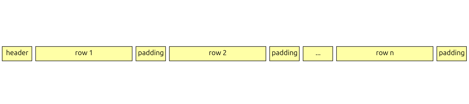
The first section is the header, and it contains information about the image data. Programs use the information from the header to interpret the rest of the file. For our purpose, we only use the header to find the dimensions of the image as well as the offset in the file where the rows start. We will see more about this shortly.
After the header, the pixel-data of the image is broken up into rows and laid out in a flat array. Each pixel occupies 2 bytes (16-bits), and pixels in a single row are grouped together. As a result, the size of each row (in bytes) is twice the width of the image (in pixels). Because the bitmap format requires the length of each row (in bytes) to be a multiple of 4, a few extra bytes are added at the end of each row to pad it. The number of rows in the image is equal to its height.
Unlike modern image formats (such as PNG, JPEG etc.) the bitmap format prioritizes simplicity over everything else (such as file size), making it suitable to use with the Arduino.
Converting images to bitmaps
As a final step before writing the program, let's see how to convert existing images to bitmaps. You can follow this process to create your own graphics, QR Codes, illustrations etc. and display them on the ILI9486 LCD Shield.
Note that bitmaps themselves may encode colors in one of several formats, while we specifically need the 16-bit 5-6-5 encoding. A website that provides this is https://online-converting.com/image/convert2bmp/. Visit the website and change the color from 24 (True color) to 16 (5:6:5 RGB Hi color) while leaving the rest of the settings unchanged.
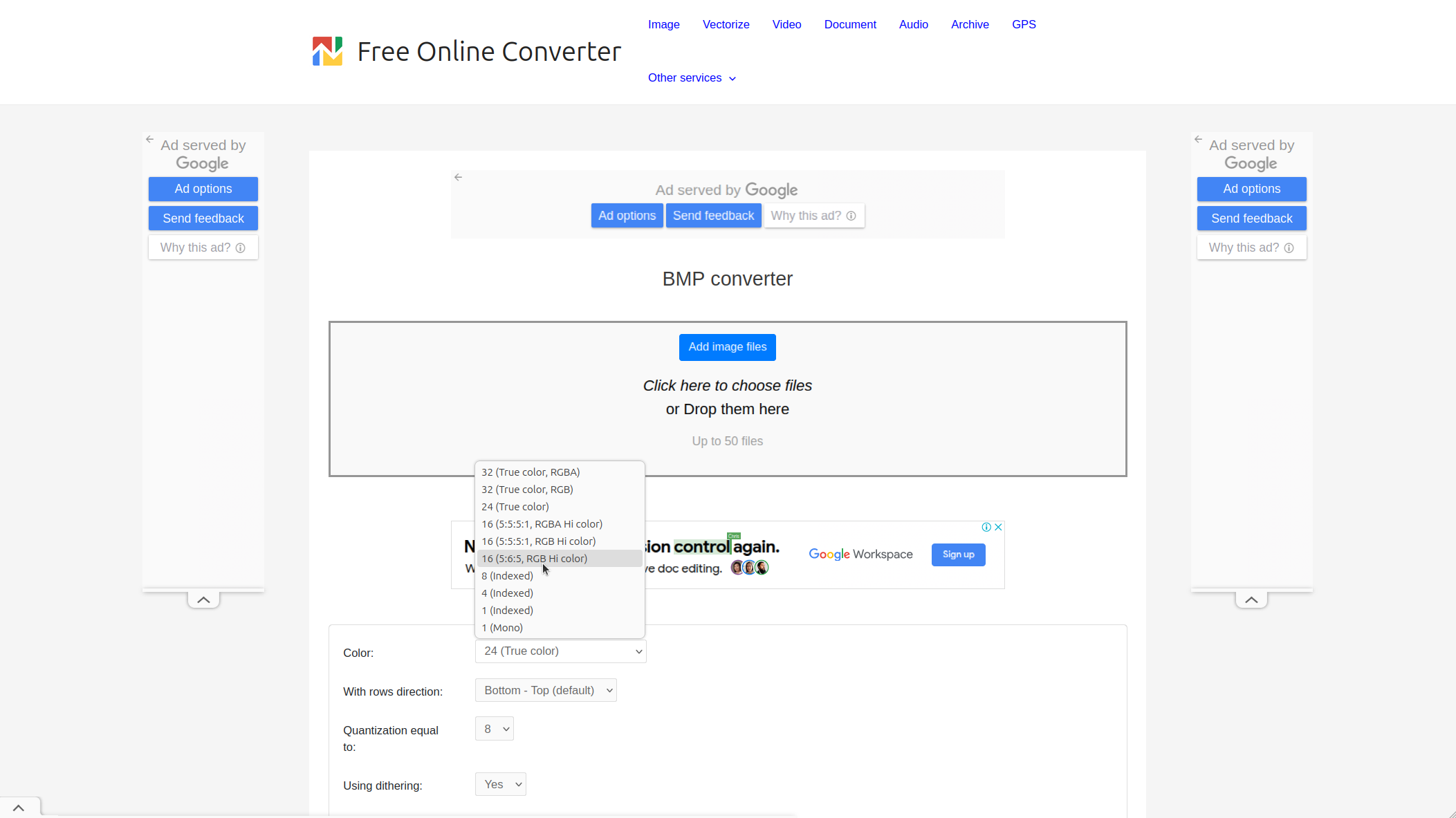
Then, upload your image file and wait for a few seconds for the conversion to complete. The process begins automatically after you select the file. Make sure to select the color mode before uploading the image.
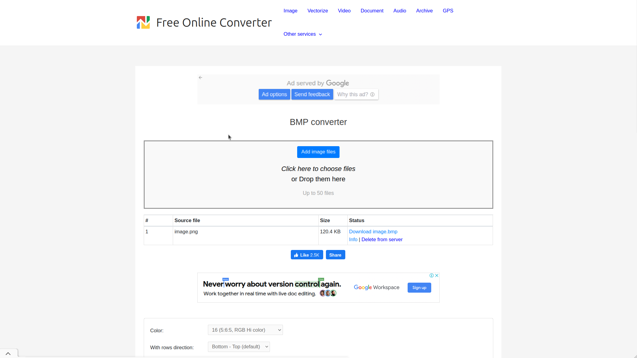
Because most images are encoded in 24-bit color and the website reduces this resolution to 16-bit, the colors might look slightly different in the result. Make sure to open the downloaded result in an image viewer to ensure that the colors still look acceptable.
Drawing stored bitmaps to the display
We can now write a program to read bitmaps from the SD Card and draw them on the display. The program given in this section reads a single image from the SD Card named IMAGE.BMP and draws it on the top-left corner of the screen. The dimensions of the image don't matter as long as it fits completely within the display. For improved flexibility, the entire code to read and draw the image is present in a separate function which can be re-used for other images as well.
Start by adding the boilerplate code for driving the ILI9486 LCD Shield and SD Card -
Note the inclusion of the constants.h file. The contents of this file, as well as how to create it, was given in the second part of this series. Next, create the setup and loop functions as shown -
As before, the setup function starts by initializing various objects. It then checks for the existence of the IMAGE.BMP file and calls the no_file function if it does not exist. If the file does exist, the show_image function is called to draw it on the display. The loop function is left empty as the program does not have any repeating tasks.
The code for the no_file function is given below -
The no_file and invalid_file functions are similar to each other, and differ only in the error message they print. Both the functions print their respective error messages on the Serial Monitor as well as the display and use a while(1); loop to prevent the program from moving forward.
Finally, add the code for the show_image function -
The function first declares variables to store the offset, dimensions and padding of the image. An additional flag calledflipped is also declared and initialized, which stores whether the order of the rows are flipped. The default order of rows in the file is bottom to top, but they can also be present from top to bottom.
Next, the offset and dimensions are read from the header. The offset is a 32-bit unsigned integer that starts from the 10th byte of the file. The dimensions are a pair of 32-bit signed integers that start from the 18th byte of the file. In both cases, the seek method is used with the file handle to skip to the value, and the read_n_lefunction is used to read the specified number of bytes from the file into the variable. We will see more about the read_n_le function shortly. For now, assume that it reads an integer of a specific size from the file into a variable.
After reading the values, the flipped flag is set or cleared depending on the height being negative. If the height is positive, then the rows are present from bottom to top (default order). Otherwise, they are present from top to bottom (flipped order). The value of padding is also calculated at this stage using the width of the image. On summing padding and 2*width, you should get a multiple of 4.
Finally, the seek method is used to skip to the beginning of the rows, which are read from the file one at a time. For each row, the color of each pixel is read from the file using the read_n_lefunction and drawn on the display. After finishing the pixels, the padding bytes are read and ignored.
The code for the read_n_le function is shown below -
The function accepts three arguments - a pointer to the variable to store the value that gets read, the file handle to read from, and the number of bytes to read. It contains a single loop to read the bytes from the file one at a time and assign them to the variable. If the end of the file was reached before the specified number of bytes could be read, the invalid_file function is called to report the error.
In particular, the variable to which the value is assigned is treated as an array of bytes rather than a single integer. Every time a byte is read from the file, we index into this array and copy the byte from the file to this location.
The suffix le is added to the function name to indicate that the bytes are treated as being in little-endian notation, where the higher bytes are present before the lower bytes. This is in contrast to big-endian notation, where the higher bytes are present after the lower bytes. If the above function were to instead follow big-endian notation, it would be re-written as follows -
The complete code is given below -
The complete code can be found here on Github.
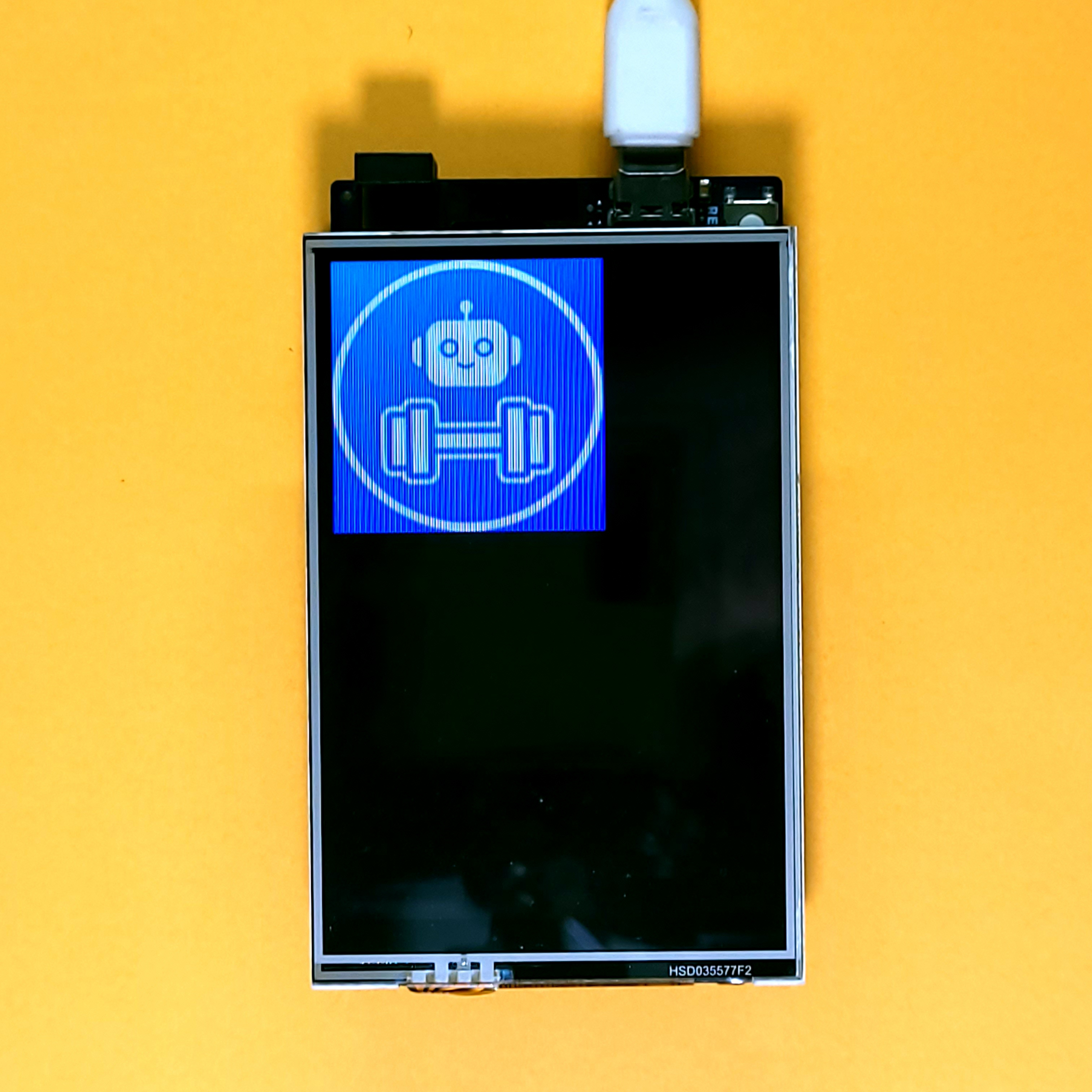
To use the code, create a BMP file named IMAGE.BMP and move it to the SD Card (make sure that the image completely fits on the display). You could use this image initially to test the program. To download the image, click the "Download Raw" button.
Plug the SD Card into the ILI9496 LCD Shield and upload the program to the Arduino. If all goes well, you should see the image drawn at the top-left corner of the display.
Final Thoughts
After reading this blog (and the previous one), you should have a fairly complete idea of how to use an SD Card with the TFT LCD Shield. Combining images with text-files and persistent storage can be a powerful tool to enhance the richness of your projects, especially when used creatively.
Hopefully, you were able to follow along and try out the example given in this blog on your own. Please feel free to share your questions and suggestions in the comments below! The next part moves towards concluding the series by creating a Paint app with the TFT LCD Shield and Arduino. The final part shows how to use the TFT LCD Shield to build the popular Tic-Tac-Toe game.