Creatively using text-files with an SD Card on a 3.5 inch TFT LCD Display and Arduino (Part 3 of 6)
By Aditya
/
July 2, 2024
This blog shows how to use an SD Card with a 3.5 inch TFT LCD Shield (driven by an ILI9486 driver) and an Arduino UNO R3/R4/Mega for beginners. It is the third of six parts, and shows how to get started with the SD Card along with text files and use them in creative ways. It contains three sections. The first section shows how to prepare the SD Card for use with the library and introduces the associated SD Card library. The second section comprehensively explains how to read/write text files on the SD Card using a builtin example. The third section demonstrates some practical applications using text files with the TFT LCD Shield. The procedure to display images (bitmaps) is shown in thenext blog.
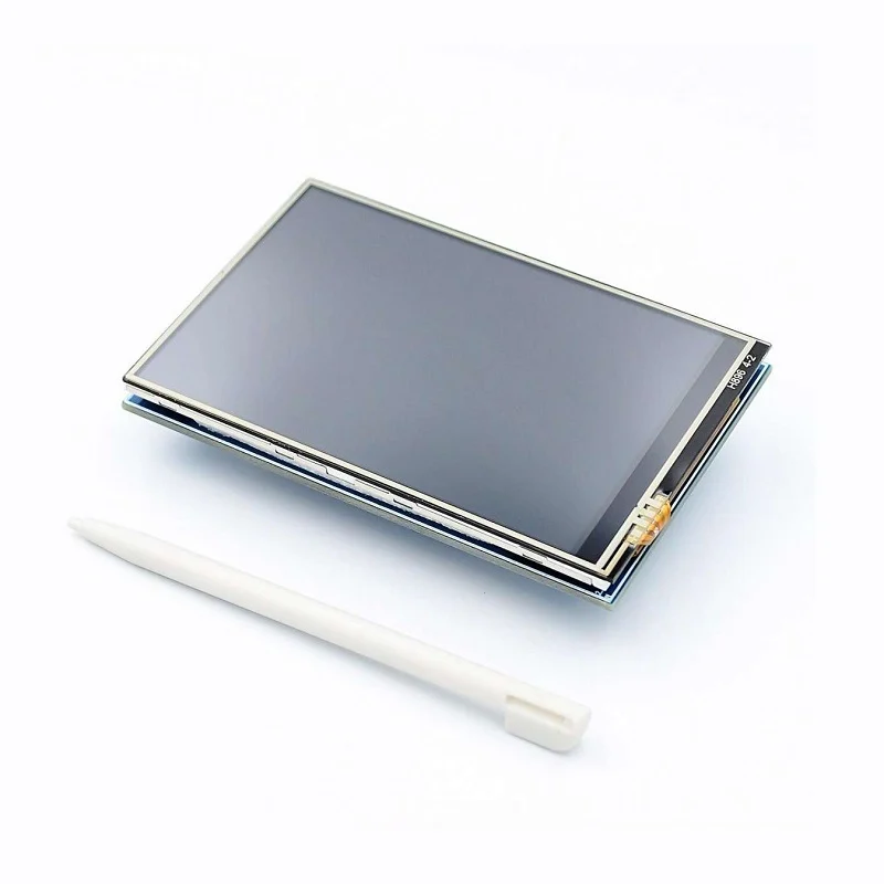
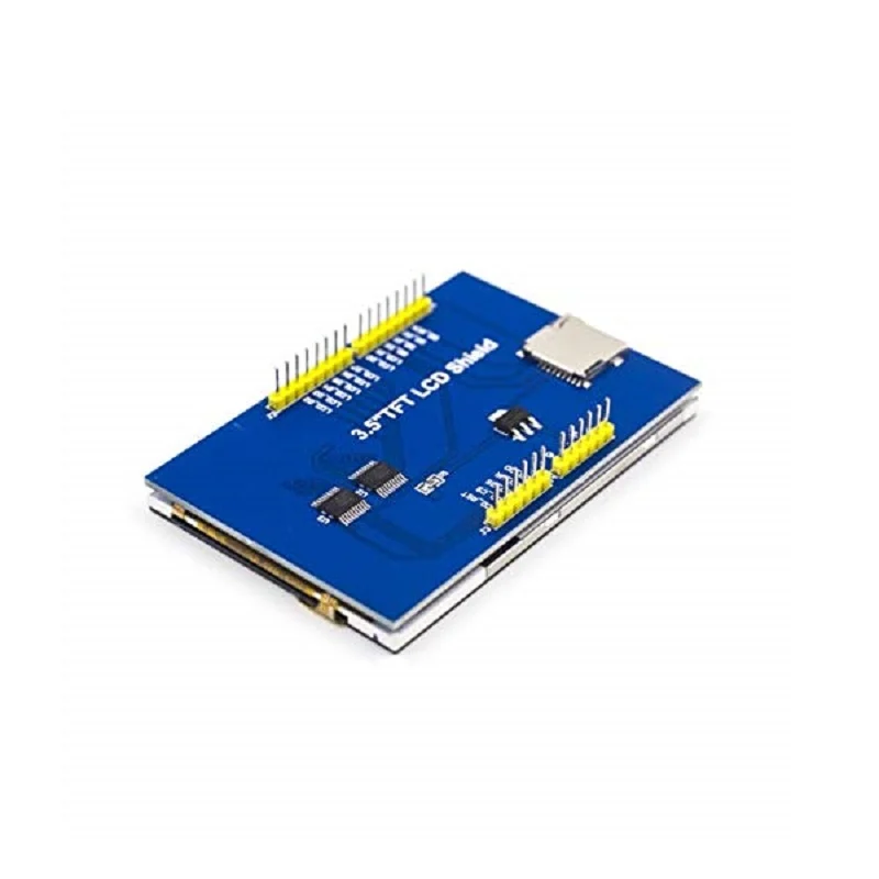
The ILI9486 TFT LCD shield has a thin film transistor (TFT) liquid crystal display (LCD) with a generous resolution of 480x320 pixels & 16-bit color depth (65,536 unique colors), a builtin touchscreen, and abuiltin SD Card slot. It is sold under different names, a popular one being ILI9486 MCUFRIEND TFT LCD Shield, and its form factor and low-cost make it a very attractive option to add rich display capabilities to your Arduino projects.
This is a comprehensive series of six blogs about interfacing a 3.5 inch TFT LCD Shield with an Arduino Board (including the newer UNO R4 Minima/WiFi). For an introduction to the display module and the libraries, refer to the first part of this series. To see how to calibrate and use the touchscreen, refer to the second part of this series. The next part of this series shows how to use the SD Card to store and display images. The fifth and sixth parts of this series shows how to use the TFT LCD Shield to create a Paint app (including a color picker, size picker and canvas) and the popular Tic-Tac-Toe game.
All the examples given in this blog (and series) have been tested on the Arduino UNO R3, Arduino Mega, Arduino UNO R4 Minima and Arduino UNO R4 Maxima. This blog uses the Adafruit GFX, Adafruit Touchscreen and MCUFRIEND libraries for performing various tasks with the displays, and the SPI library and SD Card Library to communicate with the SD Card.
Let's get started!
Briefly recapping the previous parts
The first part of this series went over the hardware components of the ILI9486 TFT LCD Shield, and showed the libraries required to operate it (along with their installation). It also covered the software architecture used to drive the display and ran some builtin examples as well as our own programs to verify its working.
The second part of this series picked up from there and comprehensively explained what calibration meant in the context of the ILI9486 LCD Shield's touchscreen. It also provided a program to implement the same, along with a video demonstrating the usage of the program.
This blog shows how to use the builtin SD Card slot on the Shield to store text files.
Preparing the SD Card and introducing the library
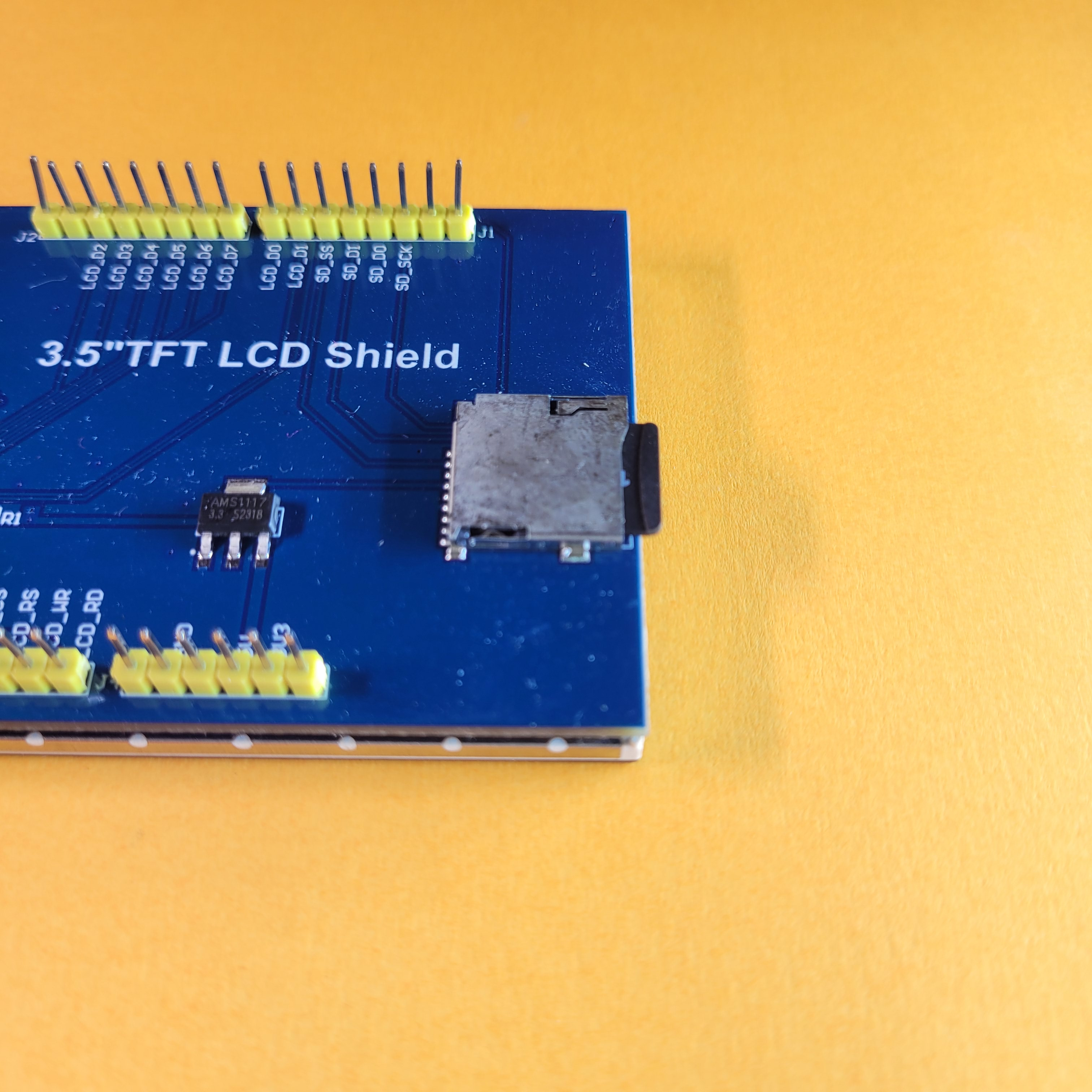
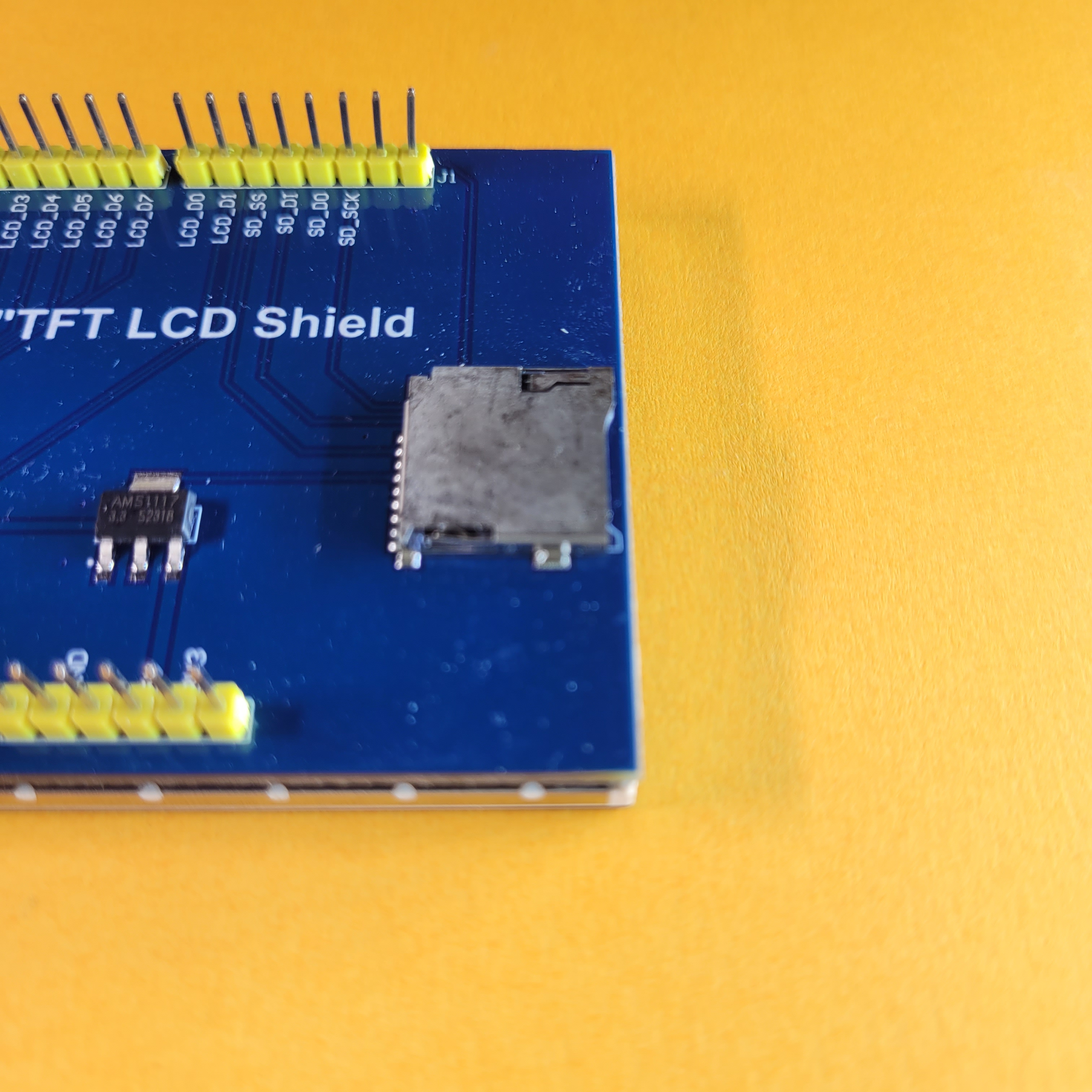
This section shows how to prepare the SD Card for use with the ILI9486 TFT LCD Shield, and introduces the library used to communicate with the SD Card on the TFT LCD Shield. Recall that the Shield has a builtin SD Card slot, which we can use to add persistent storage to the Arduino. Note that the information below is repeated in the next (fourth) part as well, and these two blogs can be read independently. If you have read the next part, you can skip this section entirely.
Formatting the SD Card
The SD Card should be formatted with a FAT16 or FAT32 filesystem, with a single partition only. This is a mandatory step to perform, without necessarily getting into the technical details of formatting. Briefly, formatting refers to the process of configuring a storage medium so that it can be read-from/written-to by controllers (such as your PC or the Arduino). This involves "laying-out" a filesystem on the medium and partitioning it. You can read more about the history of formatting here.
There are a vast number of tutorials online that already explain how to do this, but a brief summary of the steps are shown below for different operating systems. Irrespective of your operating system, you will need an SD Card slot on your Laptop/PC/Mac, or an external SD Card reader if one is not available.
Formatting on Windows
Open the file manager program and navigate to the newly connected drive (this is how Windows should present the SD Card once its plugged-in). The formatting process clears all the data in the SD card, so make sure to select the correct one (especially if multiple devices are connected).
Right-click on the drive and select the format option. Make sure that there is only one partition and other information (such as capacity) are correct. For the file-system option, select the FAT filesystem. After this, click start to begin the process.
Once completed, the card is ready to use.
Formatting on Linux (Ubuntu)
Open the Files program (Nautilus), and right-click on the drive that appears. From the drop-down, select the format option to open the formatting wizard. Close the Files window and select the option labelled FAT. You can optionally provide a name for the drive as well. After this, click next and follow the steps to finish the formatting process.
Once completed, the card is ready to use.
Formatting on Mac
Open the Disk Utility program and select the SD card from the left pane. The formatting process clears all the data in the drive, so make sure to select the correct one (especially if multiple devices are connected).
Click on the Erase option and select FAT in the options that come up. Finally, click Erase to begin the process.
Once completed, the card is ready to use.
Understanding the usage of the SD Library and pin connections
The library used to communicate with the SD Card is the SD Library that is included with the Arduino IDE by default. On PlatformIO, this can be included by adding arduino-libraries/SD to the lib_deps section. The following snippet shows the basic usage of the SD Library -
Note that the SPI library is included before the SD Library. This library is also included with the Arduino IDE by default.
First, the SD object is initialized in the setup function using thebegin method. It accepts a single argument - the chip-select pin of the SD Card (in case of the ILI9486 LCD Shield, this is pin 10). The method returns true if the initialization was successful and false otherwise. This should be checked before using the SD object further.
Next, the exists method is used on the SD object to check if a file exists. It accepts a single argument - the name of the file (as a string) to find. It returns true if the file exists and false otherwise.
After this, the open method is used on the SD object to open a file for reading. It accepts two arguments, which are the name of the file (as a string) and the mode to open it in. The latter can be either FILE_READ (allows reading only; does not create the file if it does not exist) or FILE_WRITE (allows reading and writing; creates the file if it does not exist). The method returns a file handle of type File, which refers to the opened file.
In an if-statement, the handle evaluates to true if the file was successfully opened and false otherwise. This should be checked before performing further operations on it. Note that the FILE_WRITE mode opens the file in append mode if it already exists, i.e. existing data is not cleared when the file is written to.
Files on the SD Card can be treated as a sequential array of bytes. Each file has a size, which corresponds to the number of bytes in the array. The file handle keeps track of this as well as the location of the current character being processed.
This way, the file handle can be used in a manner similar to the Serial object. Methods such as write, print and println can be used to write to the file. Whenever a character is written to the file, it is placed at the current location and the location is incremented (this happens automatically). To manually get and set the current location, the position and seek methods can be used.
To read from the file, the read and peek methods can be used. Theread method returns the character at the current location and automatically increments the location, while the peek method returns the character without incrementing the location. To check if the file has any characters left to read, the available method can be used.
After using the file, the close method can be used on the file handle to close it, which also saves all changes made to it. Detailed documentation for the SD Library is available at https://www.arduino.cc/reference/en/libraries/sd/.
In the coming sections, we will see more about the SD Library and its usage with the display and touchscreen to build useful programs.
Filename considerations
Before moving onto writing programs, it is necessary to know the constraints imposed by the library (or by the FAT filesystem) on filenames -
- Filenames can be no longer than 12 characters, including the extension. Any files with longer names will have their name truncated by the library when being referred to. If multiple files exist with long names and matching prefixes, the library will follow undefined behavior while truncating their names. Consequently, it is recommended to keep all filenames below 12 characters. In case of nested files (within directories), the name of each individual directory/file in the path should be less than 12 characters long (their combined length may exceed 12 characters).
- Filenames are not case-sensitive, including the extension. The library changes all names to upper-case while referring to files. If a mixed-case/lower-case name is provided to any of the methods/functions, it gets converted to upper-case before getting used. If a file exists on the SD Card with a mixed-case/lower-case name, it is treated as being in upper-case by the library.
- The root of the filesystem on the SD Card is referred to with /. Because of this, a file named 1.TXT that lies in the SD Card can be referred to as either
1.TXTor/1.TXT, and another file named2.TXT in a folder named nested can be referred to as either/nested/2.TXTornested/2.TXT.
How to get started with the SD Card library using a builtin example
This section walks through a builtin example that comes with the SD library to demonstrate its usage. Before writing our own program, it is a good idea to run a builtin example to ensure that the SD Card is in working condition. The builtin examples are known to work, allowing any problems that come-up to be narrowed down to the SD Card or Shield.
It is recommended to know how file IO works on a regular PC before reading this section, but not strictly required. Here is a good place to start.
To start, open "File" > "Examples" > "SD" > "ReadWrite" in the Arduino IDE. The selected example performs the following tasks -
- Create a file in the SD Card (open a file in write mode).
- Write to the file that was created.
- Close the file.
- Re-open the file (in read-only mode).
- Read the contents of the file and print it on the Serial Monitor.
- Close the file.
This is a comprehensive and complete set of operations that can determine if the hardware is in working condition. Before uploading the program, make the following change within the setup function -
This changes the chip-select pin from 4 to 10, which is what the ILI9486 LCD Shield uses on the Arduino UNO R3/R4 or the Arduino Mega. Without this change, the program will not work. Finally, plug the shield into your board, insert an SD Card into the shield, upload the program and open the Serial Monitor. If all goes well, the following should be printed -
After making sure of this, disconnect the Arduino from your PC and remove the SD Card from the shield. While it is not strictly required to power the circuit off before removing the SD Card, make sure that the program is not reading from/writing to the SD Card before removing it.
After inserting the SD Card into your PC, you should see a single file called TEST.TXT (along with any other files that were already present on it). The file should contain a single line - "testing 1, 2, 3." which matches the output on the Serial Monitor. The line is repeated multiple times if the example was run multiple times.
In case the initialization fails, the problem could either lie in the SD Card or the reader on the ILI9486 LCD Shield. Ensure that the SD Card is formatted correctly, its pads are not worn out and that it is firmly inserted into the reader. Try running the example with a different SD Card to make sure that the problem does not lie in the reader (don't forget to format the new SD Card).
Let us go through the program in greater detail -
First, the SPI and SD library are included (as shown in the previous section). Next, an instance of the File class is created in advance.
In setup, the Serial object and SD object are initialized. If the SD initialization fails, then the program reports this on the Serial Monitor and freezes.
After this, it opens the test.txt file and appends the line "testing 1, 2, 3." to it. The file is closed after completing this operation. In case the file could not be opened/created, the program reports it on the Serial Monitor.
Finally, it re-opens the file for reading. It reads characters one at a time and prints them to the Serial Monitor until the file has been fully read. In case the file could not be opened, the program reports it on the Serial Monitor.
Running this program should make the basic usage of the library very clear. For more information, you can read the complete documentation of the SD and File classes at https://www.arduino.cc/reference/en/libraries/sd/. We can now move onto writing our own programs for using text files.
Practical examples for text files with the ILI9486 LCD Shield and SD Card
This section shows how to work with text files using the SD library through some practical examples. We start with text files because they are simpler than images and can be used creatively with the ILI9486 LCD Shield. It is quite obvious what images can be used for, but text files are useful in their own way, such as storing configuration data or logging measurements. Both of these uses are demonstrated in this tutorial
Storing configuration data on the SD Card
Let us now see an example of how configuration data can be stored on the SD Card separately from the program. Configuration data refers to any data which controls how the program runs, similar to thesettings on an Android phone. This data is read by the program and used to determine how it should execute. In many cases, it is also possible for the program to update the configuration data for future executions (by taking input from the user).
Consider a program that draws three squares on the display, using colors provided in a configuration file. The colors of the squares can be changed by changing the contents of the configuration file, without modifying the program.
Assume that the file is named CONFIG.TXT. It must follow the format shown below -
The placeholders c1, c2 and c3 must be replaced with actual colors, such as -
The colors shown above are hex representations of the 16-bit color codes for red, green and blue. This method of encoding colors was shown in the first part of this series. Ideally, the program should also be robust enough to handle the following input -
The second example includes extra spaces, irregular cases, and even C-style comments at the end of each line. Let us see a program that can use this information in this file to draw the squares.
Start by creating a new project and adding the constants.h file to it. Add the following code in it -
The procedure to create the file, as well as its explanation was given in the second part of this series. In brief, it contains constants that are used throughout the program, and are kept separate from the main file for the sake of readability. The constants are divided into three categories - those used to operate the display, the touchscreen, and application-specific values. The above snippet does not include any constants in the third category, as our program does not need them.
Moving onto the main file, add the following code to it -
The above code uses the SD Library to open and read the configuration data from an SD Card plugged into the TFT LCD Shield. It then uses this information to draw the squares on the display and color them. Let us look at it more closely.
The complete code can be found here on Github
Library inclusion
These lines include the libraries necessary to drive the display, SD Card as well as the constants.h file. The process to install and use these libraries was shown in the previous parts as well as earlier in this blog.
Global variables
These lines include the creation of the tft object and the variables c1, c2 and c3, which are used to drive the display and store the colors of the three squares respectively.
Setup function
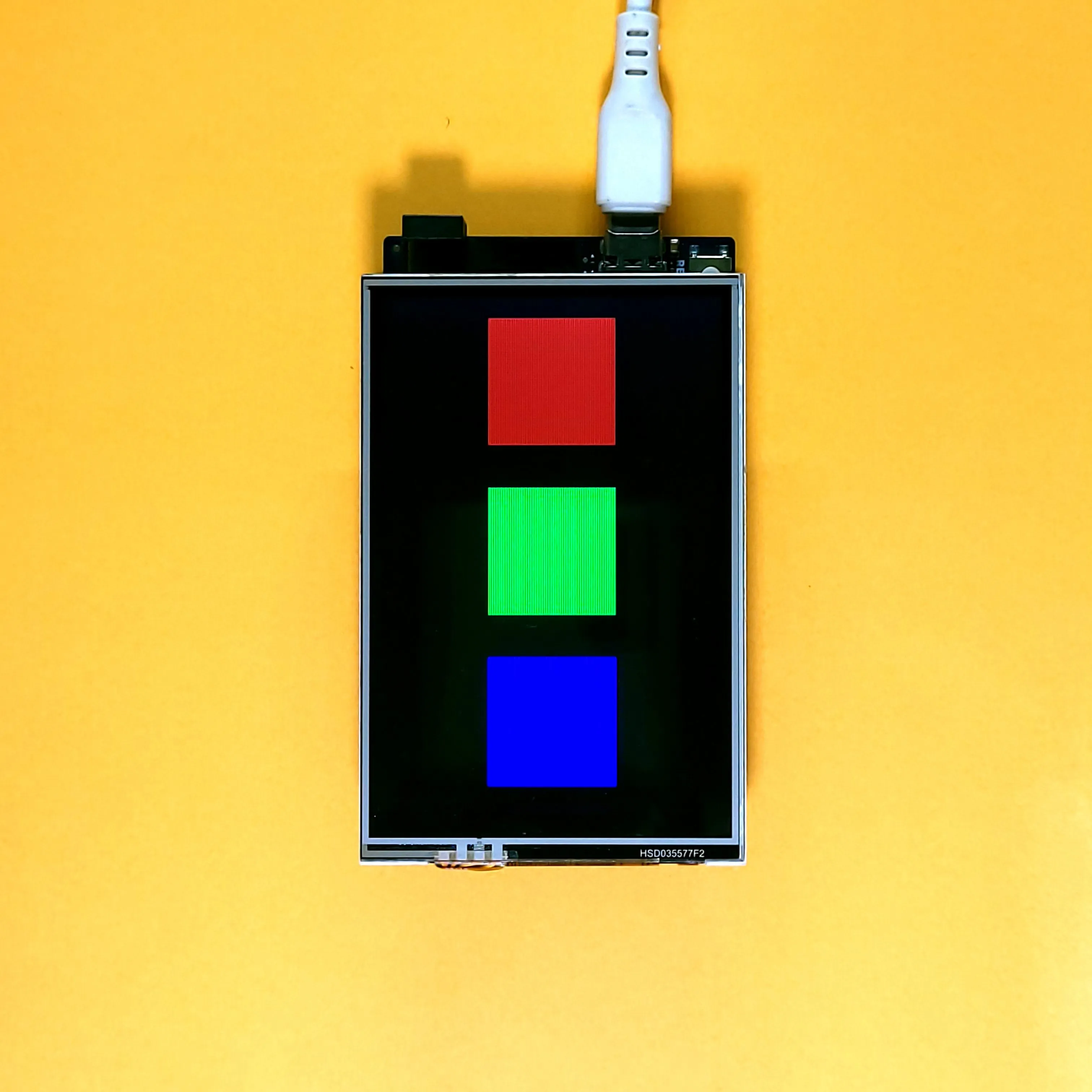
The setup function initializes the Serial and tft objects and fills the display black (to clear it). It then initializes the SD object for communicating with the SD Card, and calls the no_config function if this fails. After this, it opens the CONFIG.TXT file and reads & parses it using the parse_config function. After this function completes executing, the color of the squares get stored in the variables c1, c2 and c3. Finally, the three squares are drawn on the screen using the fillRect method. The squares have the same dimensions (120x120 pixels) and lie on the same column (100 pixels from the left edge). They are placed 160 pixels apart from each other. The loop function is left empty.
Helper functions
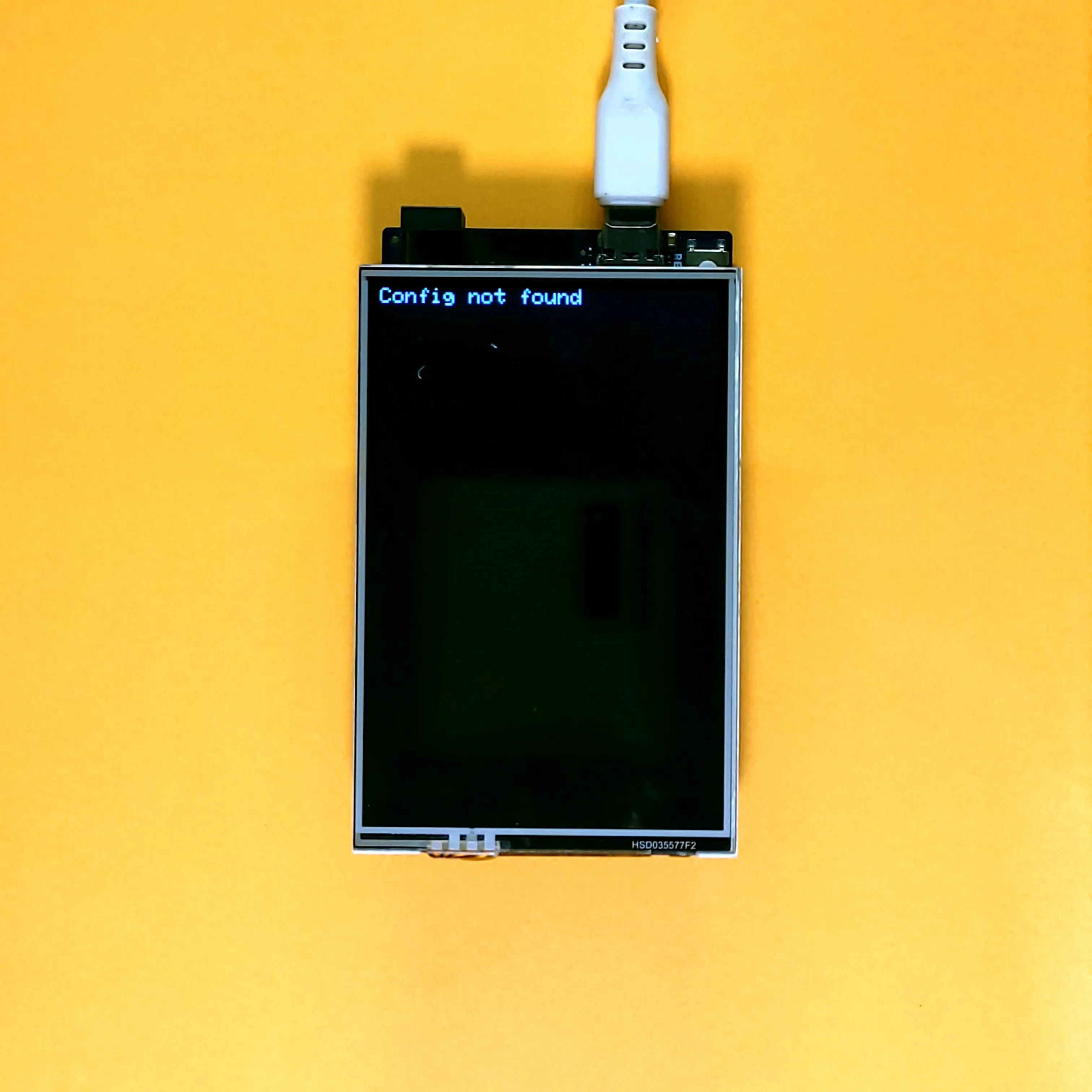
These lines contain the no_config and invalid_config functions, which are used by the setup and parse_config function respectively to indicate the absence of the config file or an improperly formatted one. They print their respective error messages on the Serial Monitor as well as the display, and halt the execution of the program using an infinite loop.
Parsing the configuration file
The parse_config function is used to parse the config file and assign values to c1, c2 and c3. It starts by declaring the two arrays named key and value, which are used to store the key and value present on each line respectively. The key is the name of the property which is present before the =, while the value is its assigned value which is present after the =. Next, it contains a loop to iterate over the contents of the file, which can broadly be divided into 7 parts.
The first part is an inner loop that skips all characters till the first double-quote ("), which is the beginning of the key. If the end of the file is reached during this (indicated by read returning -1 instead of a valid character), there are no more properties left to read and the function returns.
The second part is another inner loop that reads the name of the key into the key array one character at a time. It keeps reading till a double-quote (") is encountered. If the end of the file is reached before a ", the invalid_config function is called to indicate that the file does not follow the proper format. The third part is yet another loop that skips all characters till the equals (=) character. As before, the file is considered to be in improper format if the end of the file is reached before an = character.
The fourth and fifth parts are for reading the value associated with the key and are analogous to the first and second loops. The fourth loop skips characters after the equals character till a double quote is encountered. The fifth loop reads the value one character at a time into the value array till the next double quote is encountered. If the file ends while either of these loops are executing, it is considered to be in an improper format.
After this, the contents of the key and value arrays are printed on the Serial Monitor for debugging. Finally, the name of the key (in the key array) is compared against known values to get the variable it corresponds to. After this, the hex number inside value is parsed into the selected variable. If the value is not a valid hex value, then the config is considered invalid.
After removing the SD card and uploading the program to the Arduino, you should see the following result -
After creating the CONFIG.TXT file on the SD Card and inserting it into the shield, you should see the following result (reset the Arduino after inserting the SD Card) -
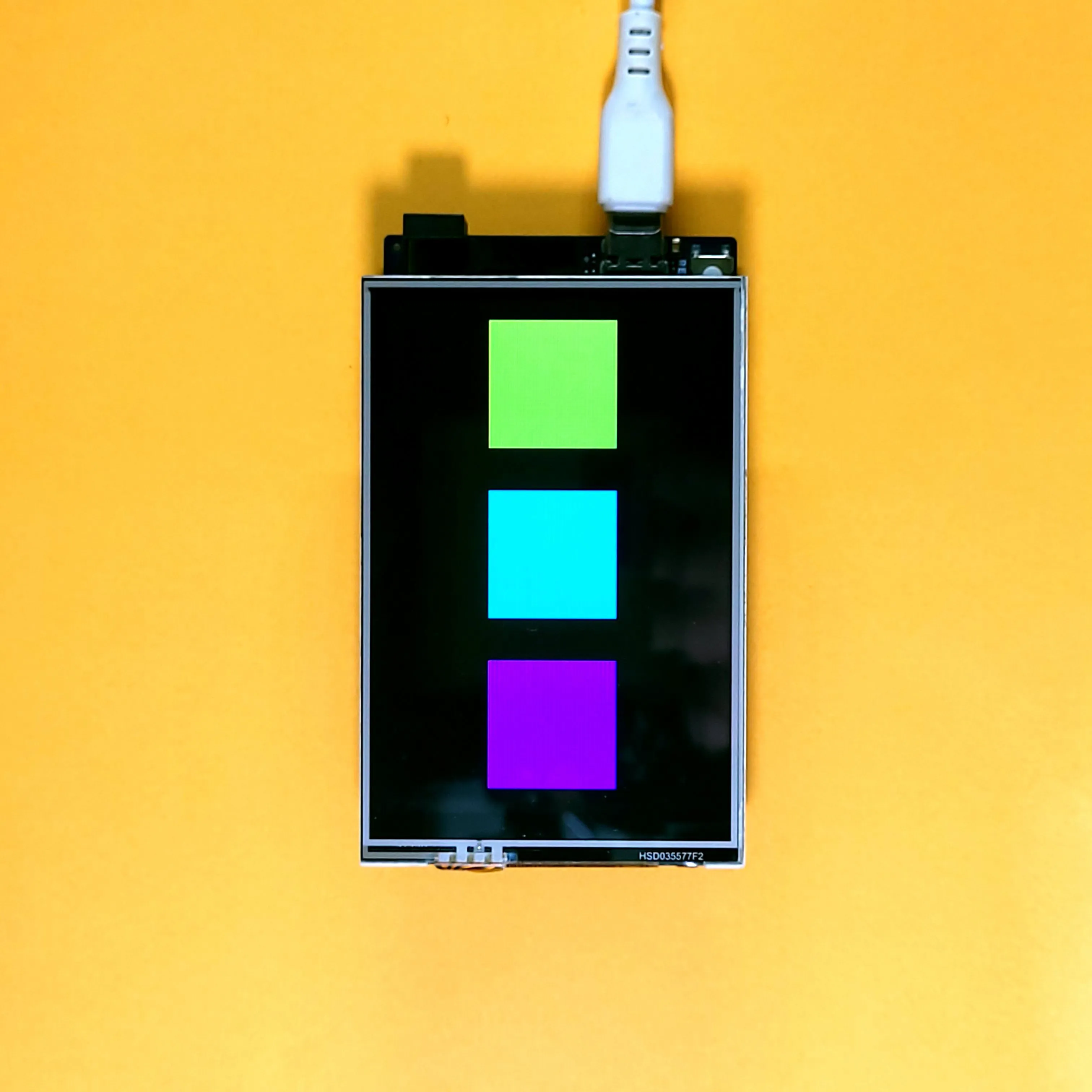
If the second example were used instead, the following is shown -
After finishing this example, you could try to extend the program to make the coordinates and dimensions of the squares configurable as well, and even make the number of squares themselves configurable. This section was only intended to provide a starting point and introduce configuration files and their merits.
Logging data to the SD Card
Let us now see an example of how data can be logged on the SD Card. Data logging is the process by which a set of events are recorded for the purpose of future analysis or diagnostics. For our demonstration, we will log the data given by the touchscreen.
This example polls the touchscreen till a touch is present. Once a touch is available, it saves the coordinates and timestamp of the touch to the SD Card every second. The data is stored in CSV format. The timestamp, x-coordinate and y-coordinate are present in different columns. Each entry is present on a new row.
As before, start by creating a new project and adding theconstants.h file to it. The contents of this file and its explanation was given earlier in this blog, while talking about configuration data.
Then, add the following code into the main file -
The above code waits for a touch to become available, and starts sampling the coordinates every second until the touch is removed. Let us look at it in greater detail.
The complete code can be found here on Github.
Library inclusion
These lines include the libraries necessary to drive the display, touchscreen, SD Card as well as the constants.h file that we created. The process to install and use these libraries was shown in the previous parts as well as earlier in this blog.
Global variables
These line include in the creation of the tft and ts objects, which are used to drive the display and touchscreen respectively. The explanation for the touchscreen was given in the second part of this blog.
Touch management functions
The above lines include helper functions to drive the touchscreen. The valid_touch function returns true if a touch is occurring. The get_touch function reads the touch coordinates and stores them in the variables given to it. The convert function converts the coordinates from touchscreen coordinates to pixel values. Finally, the to_display_mode function resets the pins shared by the display and touchscreen back to outputs after the touchscreen is used.
The detailed explanations for these functions was given in the second part of this series. The functions require the touchscreen to be calibrated, which was also explained in the second part of this series.
Setup function
The setup function initializes the Serial and tft objects and fills the display black (to clear it). It then initializes the SD object for communicating with the SD Card, and halts the program using an infinite loop if this fails. Next, it checks if the LOGS.TXT file exists, and deletes it to remove old logs. Finally, it prints a small green square on the top-left corner of the screen. The purpose of this is explained next.
Loop function
The loop function continuously polls the touchscreen for the presence of a touch. When one is detected, it reads its location and converts it to pixel-coordinates. After this, the LOGS.TXT file is opened in write mode and the color of the square is changed to red, indicating that it is not safe to power-off the device.
The timestamp (calculated using the millis function), x-coordinate and y-coordinate are appended to a new line on the file before closing it and changing the color of the square back to green. Finally, a delay of 1 second is added before polling the touchscreen again. This delay is added to prevent the Arduino from overloading the SD Card with values. It also means that tapping on the screen fast will cause some touches to get skipped.
When running the program, you will discover that the write process is incredibly fast and it is barely possible to observe the square changing colors.
The snippet shown below is an example of what the log file can contain after touching the screen at 4 points -
This example introduces how data can be logged for later analysis, and aims to provide a starting point for readers to build on.
Final Thoughts
After reading this blog, you should have a fair idea of how to use an SD Card with the TFT LCD Shield. More importantly, you should have an idea of how to use persistent storage creatively in your projects. This can act as as stepping stone to create more complicated and rich apps with the display, touchscreen and Arduino, which will be further shown in the fifth and sixth parts of this series.
I hope that you were able to follow along try out the examples given in this blog yourself. Please feel free to share your questions and suggestions in the comments below! The next part of the series focuses on image files (bitmaps) and their usage with the SD Card and TFT LCD.