Calibrating and testing the touchscreen on a 3.5 inch TFT LCD with Arduino (Part 2 of 6)
By Aditya
/
May 17, 2024
This blog comprehensively shows how to calibrate and get started with the touchscreen on a 3.5 inch TFT LCD Shield (driven by an ILI9486 driver) with an Arduino UNO R3/R4/Mega for beginners. It is the second of six parts and is divided into two sections. The first section of this blog explains what calibration is (especially in the context of the touchscreen module), and arrives at the steps needed to perform it. The second section shows a program implementing these steps and also gives a program to test the touchscreen module after calibration.
The ILI9486 TFT LCD shield has a thin film transistor (TFT) liquid crystal display (LCD) with a generous resolution of 480x320 pixels & 16-bit color depth (65,536 unique colors), a builtin touchscreen, and abuiltin SD Card slot. It is sold under different names, a popular one being ILI9486 MCUFRIEND TFT LCD Shield, and its form factor and low-cost make it a very attractive option to add rich display capabilities to your Arduino projects.
This is a comprehensive series of six blogs about interfacing a 3.5 inch TFT LCD Shield with an Arduino Board (including the newer UNO R4 Minima/WiFi). The first part of this series introduced the TFT LCD Shield and showed the hardware and software necessary to get started with it. The third and fourth parts show how to use the SD Card reader (with examples) to load/store text files and images with some interesting use-cases. The fifth part shows how to use the display to create a real project, i.e. a Paint app, including a color picker, size picker and canvas. The sixth part shows how to use the display to create the popular Tic-Tac-Toe game.
All the examples given in this blog (and series) have been tested on the Arduino UNO R3, Arduino Mega, Arduino UNO R4 Minima and Arduino UNO R4 Maxima. This blog uses the Adafruit GFX, Adafruit Touchscreen and MCUFRIEND libraries for performing various tasks with the displays, and the SPI library and SD Card Library to communicate with the SD Card.
Let's get started!
Briefly recapping the previous part
The previous part of this series did the following -
- Went over the hardware components of the display - 480x320 LCD Panel, ILI9486 IC, Touchscreen and SD Card reader, explained their purposes individually, and covered how they communicate with an Arduino (or other microcontroller).
- Explained the software architecture used while operating displays with an Arduino, i.e. the different layers into which software libraries are classified (hardware-specific, graphics and UI), facilitating smooth usage of the display.
- Introduced the Adafruit GFX, MCUFRIEND and Touchscreen libraries, which are used to operate the display with an Arduino, including their installation. In particular, the original MCUFRIEND library is not compatible with the Arduino UNO R4 Minima and Arduino UNO R4 WiFi; consequently, a fork of it must be installed.
- Showed how to check if the display works, by means of a comprehensive example (included with the MCUFRIEND library), and followed up by writing a minimal program from scratch to understand how the libraries are used.
- Showed functions to work with the 16-bit color format (converting from 24-bit, and blending two colors in a ratio).
- Ran a simple program to read raw touch measurements from the display (uncalibrated).
This blog picks up from here, and shows how to calibrate the touchscreen.
Understanding the calibration process
This section comprehensively covers the need and steps for calibrating the touchscreen on the ILI9486 TFT LCD Shield. You may choose to skip this section, and come back to it after completing the next one, which is more hands-on.
The need for calibration
Formally, calibration involves measuring certain known values and using these readings to correlate all other measurements to a standard.
To make this easier to understand, consider a thermometer that has not been marked yet. Even though the mercury column rises/falls due to an increase/decrease in the temperature, respectively; it cannot be used to measure the same, as it lacks a standard scale. The process of adding a scale to the thermometer is known as calibration.
The steps to do so, involve immersing the instrument into two substances at known temperatures (ice-water at 0 °C & boiling water at 100 °C are often used), and noting down the heights of the mercury column in each case. After this, the interval between the two points is equally divided; and the entire scale is finally labelled.
A similar task must be accomplished for the touchscreen as well. Typically, the program operating the shield expects touch locations in terms of pixel-coordinates that correspond to the display's resolution. However, the touchscreen operates using different units that do not directly align with pixels. Therefore, calibration becomes necessary to establish a conversion between these units, allowing touch inputs to be accurately translated into corresponding pixel-coordinates on the display.
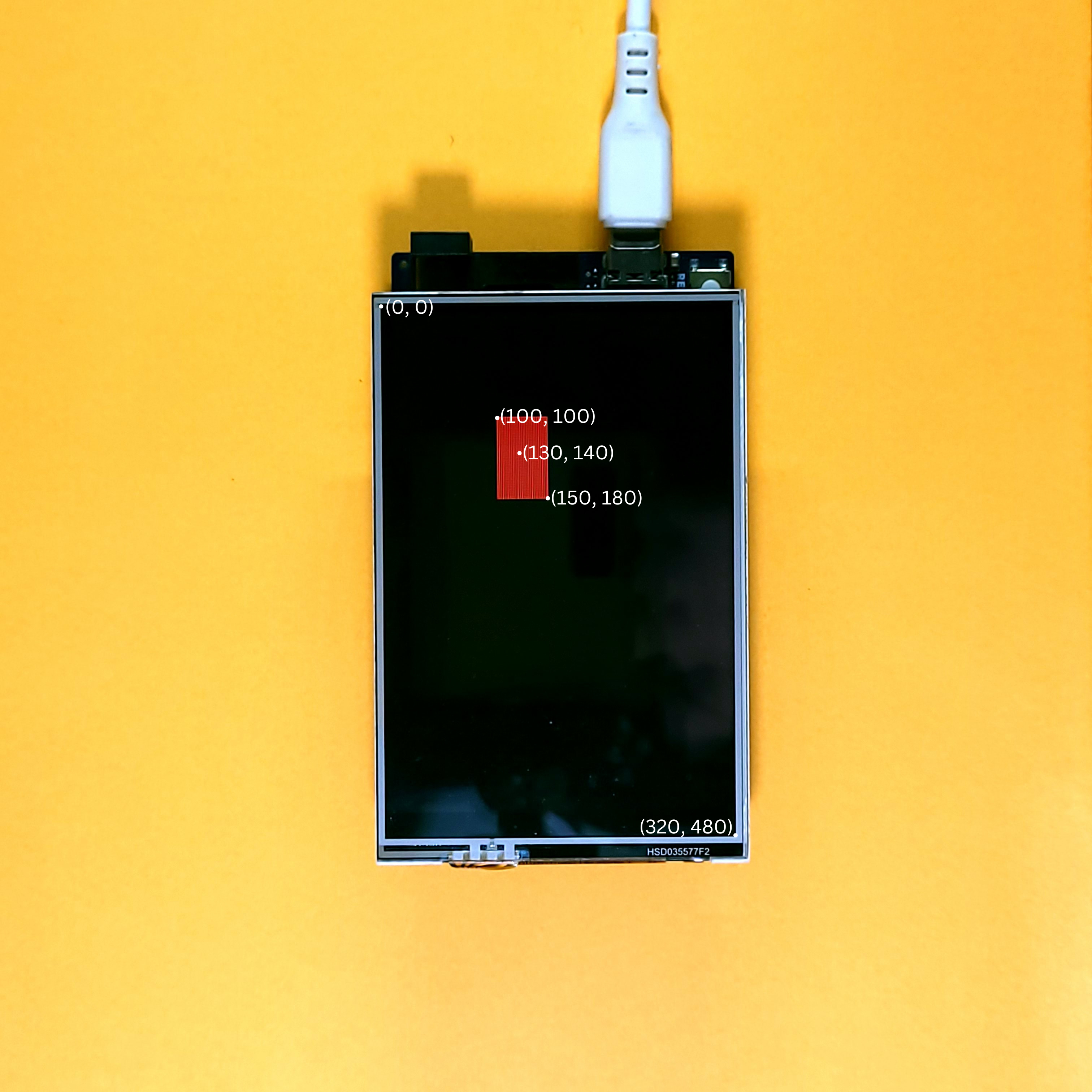
For example, a button may be drawn on the display as a rectangle with corners at (100, 100) and (150, 180). To press this button, the user may tap somewhere near its center, such as (130, 140). The below image shows this -
The touchscreen, however, may follow its own coordinates as shown -
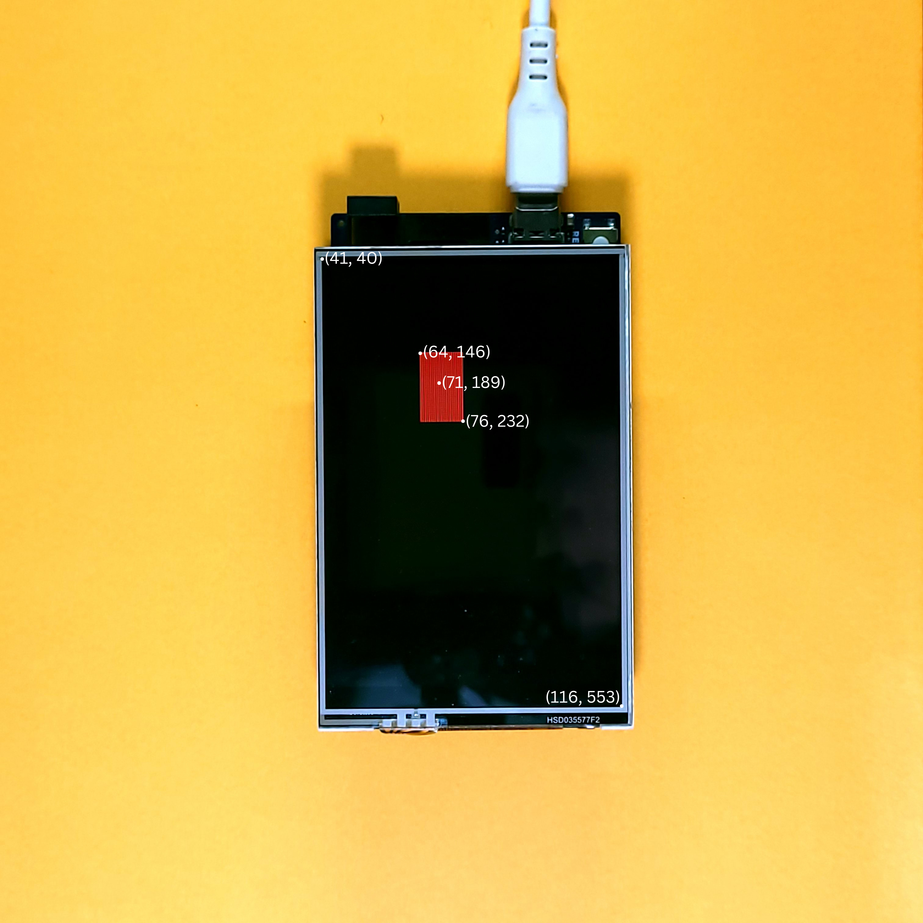
In this case, the touchscreen will report the coordinates of the tap to be (54, 190). This obviously cannot be used by the program as-is; it must first be converted to its corresponding pixel-coordinates.
Let the range [0, 319] on the display's x-axis map to [XBEGIN, XEND] on the touchscreen. Similarly, let the range [0, 479] on the display's y-axis map to [YBEGIN, YEND] on the touchscreen. The values XBEGIN and XEND denote the raw-coordinates on the extremities of the x-axis, while the values YBEGIN and YEND denote the raw-coordinates on the extremities of the y-axis.
Continuing the above example, let XBEGIN = 12 and XEND = 116. Using this information, we can convert the raw-coordinate 54 to its corresponding pixel-coordinate 130. A similar approach can be followed for the y-axis as well.
Therefore, the coordinate 130 on the display's x-axis maps to the coordinate 54 on the touchscreen.
To conclude, calibration involves finding the values of these 4 constants and defining some logic to convert the raw-coordinates to pixel-coordinates using these.
Using the map function to convert the readings
By now, we understand that calibration will produce 4 values (2 per axis) which will be used to convert the raw-coordinates to pixel-coordinates. In order to use these values, however, we need a utility function that can map values from one range to another. Conveniently for us, the Arduino library already includes a function to do exactly this, which is the appropriately named map function. Its usage is shown below -
The aforementioned code only works when XBEGIN is less than XEND. If XBEGIN were instead greater than XEND (indicating a flipped axis on the touchscreen), the following code should be used -
Note that this is not the same as the snippet shown below -
This is because of an implementation detail of the map function when dealing with unsigned integers (as in our case). For the mathematically inclined, the map function is defined as follows -
map(v, fromlo, fromhi, tolo, tohi) = tolo + (tohi - tolo)(v - fromlo)/(fromhi - fromlo)Using the map function, we can define our own function to convert the raw-coordinates to pixel-coordinates -
The above function accepts pointers to the raw-coordinates, and uses these to modify them in-place. The constrain function is invoked prior to map to guarantee that the values fall within the specified range. This is necessary as the recorded values of XBEGIN and XENDmay deviate slightly from the real values. This does not impact the output of the conversion, but can lead to integer underflow if not addressed.
For instance, if the recorded value of XBEGIN was 103, and the raw x-coordinate passed to the function was 101, it could result in an underflow error. This error would yield 65,535 as the pixel-coordinate if not corrected.
Let us now see the steps to find the values of XBEGIN, XEND, YBEGIN and YEND.
Steps for touch calibration
A simple and reliable way to get the values of the 4 constants is to measure the raw-coordinates at the 4 corners. To reduce human-error, multiple readings can be taken for each corner and averaged. This process may appear tedious, but has to be done only once for a display, as the values don't change.
The following steps show a brief summary of the calibration process -
- Repeat the following steps for each corner -
- Assign the average of the raw x-coordinates of the top-left and bottom-left targets to
XBEGIN.- Draw a target and record the raw-coordinates of the target by getting the user to tap on it. The target is a simple shape that indicates where the user should tap.
- Calculate the average of the readings for each axis to get the most accurate values.
- Assign the average of the raw x-coordinates of the top-right and bottom-right targets to
XEND. - Assign the average of the raw y-coordinates of the top-left and top-right targets to
YBEGIN. - Assign the average of the raw y-coordinates of the bottom-left and bottom-right targets to
YEND.
Completing this process will yield the values of XBEGIN, XEND, YBEGIN and YEND for us to use in future programs along with the convert function. The purpose of doing these steps will become clear as we explore the code.
Touch calibration code
This section introduces the program to calibrate the touchscreen on the ILI9486 TFT LCD shield by implementing the steps shown in the previous section. Before starting, make sure that you've correctly installed the libraries, as shown in the previous blog. If you wish to run the full code first, copy the constants.h file (first snippet) and main file (final snippet) and upload them to your Arduino.
The final result is shown below -
Start by creating a file called constants.h to store all the constant declarations. In the Arduino IDE, you can do this by clicking the toggle on the right side of the window, as shown -
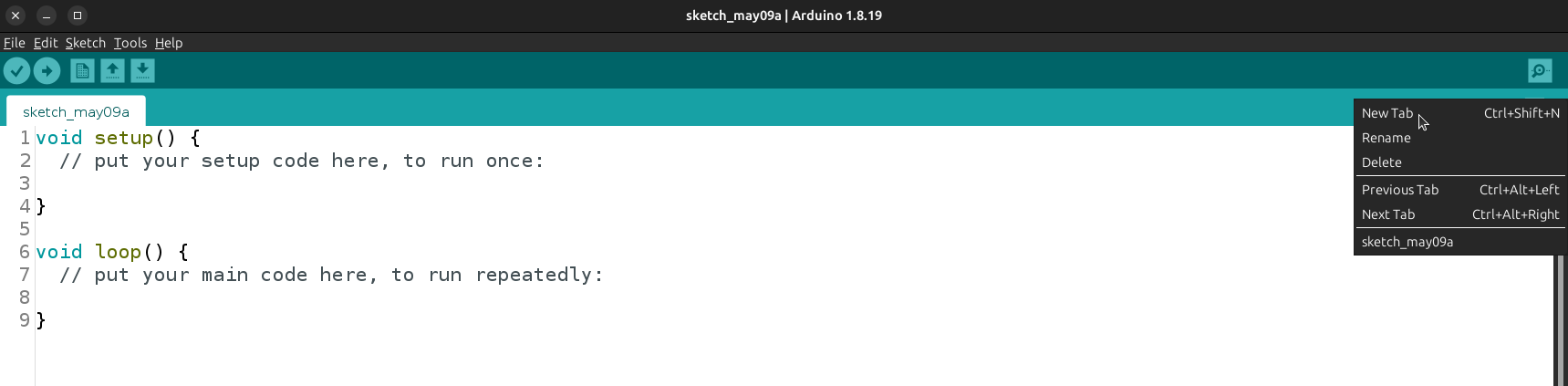
A separate file is created with the intent to improve readability. Moreover, these constants will be used in other projects as well, and it is a good idea to keep them in a different file for easy copying/tracking. Add the following code to it -
The constants are categorized into three groups. The first group is used while operating the display (this includes common color codes and the dimensions of the display). The second group is used while operating the touchscreen (the bounds on the range of valid pressure and the GPIO pins). The third group contains values specific to the application being built (in our case, the calibration program).
Henceforth, the terms target and crosshair will be used interchangeably, because the target will be drawn as a square with a cross inside. CROSSHAIR_W denotes the width of a crosshair, whileCROSSHAIR_H denotes its height. CALIBRATION_TOUCH_CNT andCALIBRATION_TOUCH_PERIOD_MS denote the number of measurements per target and cool-down period between readings, respectively. The exact usage of these constants will be seen as we proceed forward.
Moving on from the constants, add the following code to the main file -
The array crosshair_coors stores the coordinates of the centers of the 4 crosshairs, going in the order - top-left, top-right, bottom-left and bottom-right. As the crosshairs are placed in corners, their centers are half their width (and height) away from the respective edges (in pixels).
The following image help to visualize this -
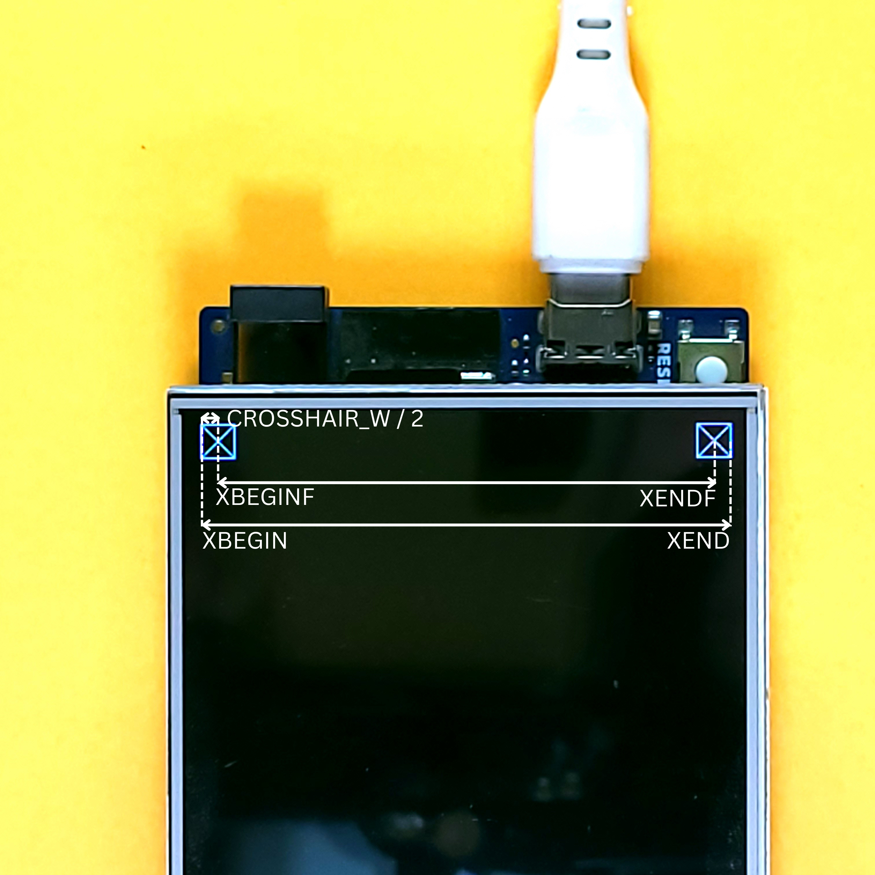
It can be seen from the images that the centers of the crosshairs (where the measurements were taken) do not truly lie on the corners of the display, only near them. Consequently, we need to get the raw-coordinates corresponding to the corners using this information. Consider only the first expression -
Recall that xbeginf and xendf are raw-coordinates that correspond to the pixel-coordinates CROSSHAIR_LEFTand CROSSHAIR_RIGHT, respectively. Using this information, we can reverse-map the pixel-coordinate 0 to its corresponding raw-coordinate, and treat this as the standard value for XBEGIN. The same process is repeated for the other 3 constants to get their standard values. Finally, these values can be printed to the Serial Monitor as shown -
The above code also prints these values to the center of the display. The complete code is shown below -
Because the calibration process should only execute once, all our code is present in the setup function and the loop function can be left empty.
After uploading this code and running it, you should be see a crosshair appear on the top-left corner of the screen. Tapping it will change its color from red to green for a short while, after which it will change back to red. Repeat this process until the crosshair turns white. Repeat this entire process for all 4 corners. Finally, the values for the constants XBEGIN, XEND, YBEGIN and YEND will be printed on the Serial Monitor as well as the display.
Make sure to save the values from that are printed on the Serial Monitor, as they will have to be pasted in the constants.h file in all other projects.
This complete code can be found here on Github
Program to test calibrated touchscreen
Before moving onto complex projects, it is a good idea to test the calibrated touchscreen with a simple program first. Create a new project using the Arduino IDE and create a constants.h file as shown previously. Paste the following into it -
Note that the application constants have been completely removed while the calibration values have been added. Make sure to replace the _ with the values printed after the calibration process.
Next, paste the following program into your main file -
The above code is a straightforward program that draws 3 red squares on the display, and reads the touchscreen to detect the presence of a touch. Whenever a touch is available, the convert function is used to convert the raw-coordinates to pixel-coordinates and printed to the Serial Monitor. If the touch lies within one of the squares, then it turns green. Make sure that you have corrected for any flipped axis in the convert function.
To make sure your screen is well-calibrated, test by tapping the centers of the squares and gradually moving to their edges. If all goes well, the squares should turn green when the tip of the stylus lies within them, and turn back to red once it is removed.
Final Thoughts
By the end of this blog, you should have a thorough understanding of what calibration is. This includes the need for calibration and how to calibrate the touchscreen on your ILI9486 TFT LCD Shield using the Arduino. You should also be comfortable with creating simple interactive graphics by using the calibrated touchscreen and LCD together, and are ready to delve deeper into graphical interfaces.
I hope that you were able to follow along and try out the demonstrations and examples yourself. Any questions and suggestions are welcome in the comments below! The next parts of this series explain how to use SD Card storage with the shield, and build projects with more complex graphics and interactivity (a Paint application and the famous Tic-Tac-Toe game).