Getting started with a 3.5 inch TFT LCD Display with Arduino (Part 1 of 6)
By Aditya
/
May 10, 2024
This blog is a tutorial on how get started with a 3.5 inch TFT LCD Shield (driven by an ILI9486 driver) with an Arduino UNO R4/R4/Mega for beginners. It is the first of six parts, and introduces the display as well as the hardware and software setup required to drive the module. It contains three sections. The first section of this blog covers thehardware components of the TFT LCD shield and their significance, the second section introduces the libraries and software patterns used to program the display module, and the third shows how to use the libraries to test the capabilities of the display module with some simple, practical programs.
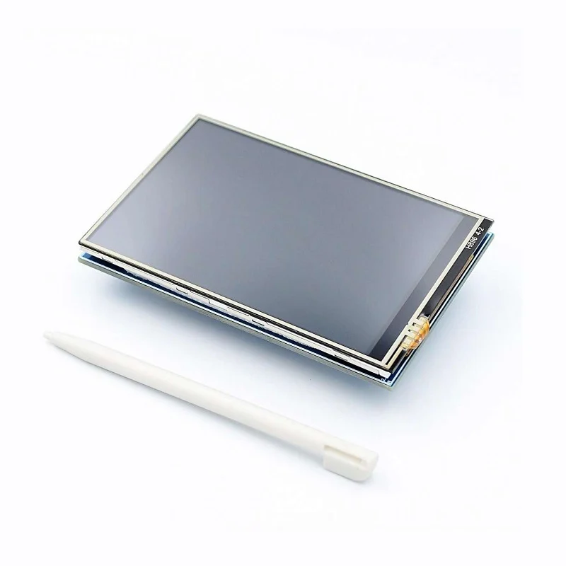
The ILI9486 TFT LCD shield has a thin film transistor (TFT) liquid crystal display (LCD) with a generous resolution of 480x320 pixels & 16-bit color depth (65,536 unique colors), a builtin touchscreen, and abuiltin SD Card slot. It is sold under different names, a popular one being ILI9486 MCUFRIEND TFT LCD Shield, and its form factor and low-cost make it a very attractive option to add rich display capabilities to your Arduino projects.
This is a comprehensive series of six blogs about interfacing a 3.5 inch TFT LCD Shield with an Arduino Board (including the newer UNO R4 Minima/WiFi). The second part of this series comprehensively shows how to get started with the touchscreen module (from calibration to testing). The third and fourth parts show how to use the SD Card reader (with examples) to load/store text files and images with some interesting use-cases. The fifth part shows how to use the display to create a real project, i.e. a Paint app, including a color picker, size picker and canvas. The sixth part shows how to use the display to create the popular Tic-Tac-Toe game.
All the examples given in this blog (and series) have been tested on the Arduino UNO R3, Arduino Mega, Arduino UNO R4 Minima and Arduino UNO R4 Maxima. This blog uses the Adafruit GFX, Adafruit Touchscreen and MCUFRIEND libraries for performing various tasks with the displays, and the SPI library and SD Card Library to communicate with the SD Card.
Let's get started!
Can an Arduino run a color display?
This question is the first thing that comes to mind for most beginners when an Arduino and color display are mentioned in the same sentence. After all, the Arduino UNO R3 uses a 16-bit microcontroller at 16 MHz, with a little over a dozen GPIOs; and does not immediately give the impression that it can run a large color display. The Arduino UNO R4 improves upon its predecessor in computing power, but still has less than 1 MB of flash, which seems minuscule compared to the size of modern graphics.
However, this is not the case, and the answer to this question depends on the project. In case where the display only shows static image(s), it is possible to pre-render the frames and store them in the Arduino's storage. As long as they can fit, these can be transferred to the display when the program runs.
Other applications may require dynamic interfaces, but are still possible to build as long as the number and complexity of calculations are small enough to fit in the flash and be performed in real-time respectively.
To summarize, applications with static images can be built as long as the pre-rendered frames fit in the Arduino's Storage, while dynamic applications can be built as long as the calculations fit in the program storage and can be executed in real-time.
Some examples of the latter, are forms with pre-rendered fonts, or a game like Pacman where only simple geometric shapes are drawn. Real-time 3D rendering is an example of what is not possible with an Arduino.
Some exceptions to this are the new Arduino Giga and Portenta (possibly more boards are released after this tutorial goes up), which have extremely capable processors closer to desktop computers, allowing for computationally-intensive applications to be built.
Hardware components of the ILI9486 TFT LCD shield
This section goes over the hardware components of the 3.5" TFT LCD touchscreen, and also mentions their relevance when it comes to using them with an Arduino (or other microcontroller) in projects. This section can help in clearing many misconceptions about displays, especially for beginners. To get hands-on immediately, you can skip this section and come back to it later.
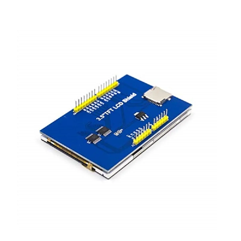
List of components on the ILI9486 TFT LCD shield
The LCD Shield contains the following components -
TFT LCD Panel & ILI9486 IC - Together, these are the most prominent components present on the shield. The thin-film-transistor (TFT) liquid-crystal display (LCD) panel is a flat grid of 480x320 pixels, with 16-bit color depth. To put that into perspective, the Apple II, a computer released in 1977 supported a maximum resolution of 280x192. The TFT stands for thin-film-transistor, which differentiates it from other Liquid Crystal Displays with low-resolution/character-only capability. The ILI9486 IC, meanwhile, is an Integrated Circuit that operates the LCD Panel according to commands that are sent by the Arduino. It communicates with the Arduino over SPI, 8-bits at a time. The IC is necessary because the Arduino does not have enough pins to control the LCD Panel directly, even with multiplexing.
Resistive Touch screen - This is a pair of layers present above the LCD Panel, that can be probed by the Arduino to sense the presence and location of a touch. It requires 4 of the Arduino's GPIO pins to operate, and its circuit is still completely disjoint from that of the display, i.e. it can be used separately from the rest of the display.
SD Card Reader - A Micro SD Card reader is included with the display, which can be used to add persistent storage. Communication is performed over SPI, but a different bus than the ILI9486 (as the SD Card only uses 2 data-lines). Consequently, its circuitry is completely disjoint from the rest of the components as well and is fully capable of being operated on its own. The advantage of having the SD Card built into the display shield is that it can offload the storage of large icons and graphics from the Arduino's limited built-in storage.
An important point to note is that the various components can be used independently from each other, despite being physically present on the shield together. This means that the shield can technically be used only as a trackpad (only touchscreen), an SD Card reader, or a read-only display.
Let us now look at the relevance of each of these components, and how they come together in greater detail.
How does an Arduino control the LCD Shield
As mentioned in the previous section, the LCD Shield has three components, each of which can be operated independently. So, how do the Arduino and shield communicate with each other? This is summarized briefly by the diagram shown below, along with its explanation -
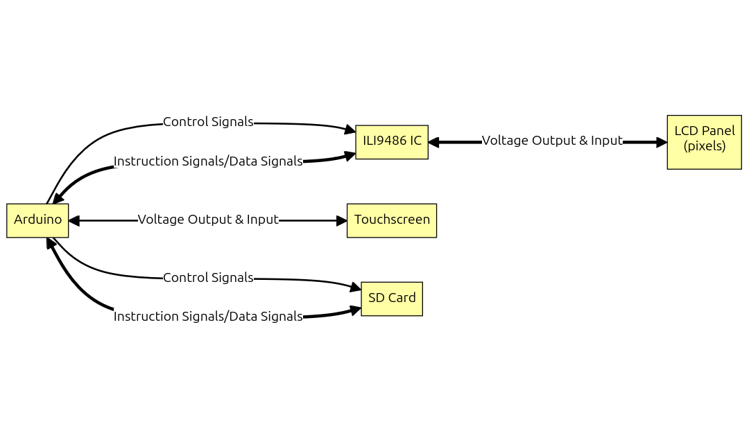
ILI9486 and LCD Interface
This diagram reveals an important point, i.e. the pixels on the LCD Panel are not directly driven by the Arduino's IO pins.
This may come as a surprise to beginners, whose might have driven some LEDs connected to the Arduino in a 1:1 manner (each LED requires one pin). Slightly more experienced makers would have have built LED Cubes/Matrices where persistence of vision was used along with multiplexing/charlieplexing to control more pixels than the number of pins on an Arduino.
The display, however, has a total of 153,600 individually controlled pixels, each with 65,535 possible states. This is simply impossible to drive directly with a normal microcontroller. Consequently, the ILI9486 driver is used to drive the pixels, while the Arduino only sends predefined commands to the driver to execute. Do note that the ILI9486 driver still uses multiplexing along with persistence of vision to control the pixels. This can be seen by trying to record it with a smartphone camera with a fast shutter-speed.
As for the method of communication, different types of displays use different standards to talk to the Arduino (or any other microcontroller), such as SPI, I2C, HDMI or even proprietary protocols, depending on the resolution and frame-rate. The ILI9486 TFT LCD Shield uses SPI with an 8-bit bus. Information is sent to/received from the display as instructions & data. Instructions are things like “draw a rectangle" or “set a pixel", while data is the information required by the instruction (such as color, or length/width).
Note that this communication needs to happen at a significant speed for any practical use, and functions from the Arduino Library (such as DigitalWrite and DigitalRead) are too slow in this case. Therefore, GPIO-banks are accessed in a much more direct manner to achieve sufficient IO speeds (to read more about this, click here). Furthermore, the display natively understands only simple commands, like drawing rectangles. Drawing complex shapes/graphics must be implemented through code/software. Fortunately for us, libraries already exist to solve these two issues, which we will see more about in the coming sections.
Resistive and Capacitive Touchscreens
As mentioned before, the TFT LCD shield includes a resistive touchscreen. This is in contrast to a capacitive touchscreen, which is common in smartphones. The latter has better precision, multi-touch, and forms a thinner layer above the display, which leads to brighter and more vibrant colors.
Despite these advantages, a capacitive touchscreen is quite expensive and requires complicated (relatively) dedicated circuits to control, making a resistive touchscreen more appropriate here.
The TFT LCD Shield uses a 4-wire resistive touchscreen, consisting of two layers of conductive material. Both the layers are designed to have increasing resistance along one axis, and uniform resistance along the other. They are placed perpendicular to each other (at right-angles to each other).
In this configuration, the following procedure can be followed to determine the position of a touch -
- A known voltage is applied across one of the layers.
- The voltage of the opposite layer is measured.
- The magnitude of the measured voltage will lie between 0 and the voltage applied initially. This can be used to get the coordinate of the touch along one of the axes.
- This process is repeated for the other layer to determine the coordinate along the other axis.
This process may appear complicated, but libraries already exist to care of these details for for us, and which we will be covered in the coming sections.
SD Card Interface
The SD Card interface uses SPI to communicate with the Arduino. It can be used with the standard SD Card Library that comes with the Arduino IDE.
Software libraries & architecture for operating displays
This section introduces the libraries that are used to drive the 3.5" TFT LCD Shield and also goes over the software architecture while using displays in-general. To get hands-on immediately, you can skip this section and come back to it later.
Responsibilities separated into different layers
As mentioned in the previous section, the TFT LCD Shield includes the ILI9486 IC, which accepts commands from the Arduino (or other microcontroller) and drives the display accordingly. The commands accepted by this driver are of a very simple nature, such as drawing lines/rectangles or changing the color of individual pixels (this property is not peculiar to the ILI9486, and is a feature of most other driver ICs).
If used as-is, it is a herculean task to create even simple user-interfaces (think of creating a modern web-browser in assembly). Various software libraries have been created to provide abstractions over these instructions, and can be broadly divided into three categories as shown below -
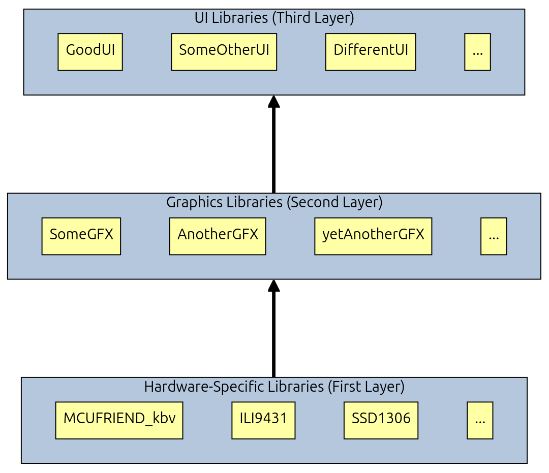
The diagram above lists a set of fictitious libraries, and divides them into three layers.
At the bottom, we have the first layer. Libraries at this layer are responsible for communicating with the display using commands which it understands natively. This layer must implement functions with a 1:1 correspondence with these commands, where each function sends the command to the display over SPI (or whichever standard that the display uses).
Next, comes the second layer. Software Libraries operating at this layer must use the first-layer libraries as building blocks to implement more complicated commands, such as drawing polygons, bitmaps, printing characters etc.
While not natively understood by the display, these commands are translated by the software libraries into the bare-bones commands the driver supports. Second-layer libraries usually interface with first-layer libraries by requiring a minimum set of functions to be implemented. For example, a graphics library may state that it requires a draw_pixel(x, y, color) function to be defined externally (by a first-layer library), for the rest of its functions to work. It does not care about the details of the implementation, as long as it is implemented.
Beyond this, complex projects may require richer user-interfaces, which are difficult to create even with graphics primitives. To solve this, widgets and the widget-tree are introduced in the third layer of responsibility. A widget is a re-usable element in a user-interface with its own appearance and behavior. Some examples of widgets are buttons, sliders, knobs, text-boxes, scroll bars etc. An application may define any kind of widgets apart from the ones mentioned above, based on its requirements.
These widgets are arranged (in-memory) in a tree. Widgets are grouped based on their behavior and arranged in layouts, which may themselves be grouped and arranged in other layouts recursively, all the way to the root of the tree. This makes arrangement, positioning and event-propagation very easy to do. Libraries at this layer work with second-layer libraries similar to before, by providing a contract where certain functions must be implemented externally for the rest of the functions to work.
Each library must adhere to the contract provided by the layer above it, i.e. it must implement the functions and classes required by the contract. This pattern can be seen for not just the 3.5" TFT LCD, but with Arduino Displays in general.
In particular, commands involved in drawing widgets are converted to graphics commands, which in turn are converted to display commands, before being executed by the driver. This method of creating abstraction is a very important tool to ease the creation of diverse projects, with their own requirements for the display.
A consequence of this is that a UI Library may be able to operate different graphics libraries, while a single graphics library may be compatible with many UI libraries.
This guide uses the following libraries for managing graphics -
| Name | Description | Source |
|---|---|---|
| Adafruit GFX | Graphics Library | https://github.com/adafruit/Adafruit-GFX-Library |
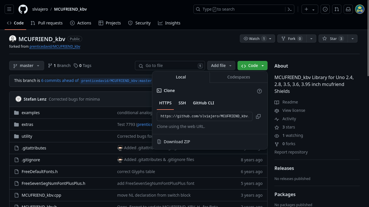
| MCUFRIEND_kbv | Hardware-specific library for ILI9486 driver | https://github.com/slviajero/MCUFRIEND_kbv (fork of the original) |
Because of the simplicity of the projects, a UI library is not used at all. To see a project with this shield that uses a UI library, see this project.
The following other libraries have also been used -
| Name | Description | Source |
|---|---|---|
| Adafruit Touchscreen | Library to use 4-wire touchscreens with Arduino | https://github.com/adafruit/Adafruit_TouchScreen |
| SD Card | Library to read from and write to SD Cards with Arduino | https://github.com/arduino-libraries/SD |
Contrasting buffered & non-buffered Displays
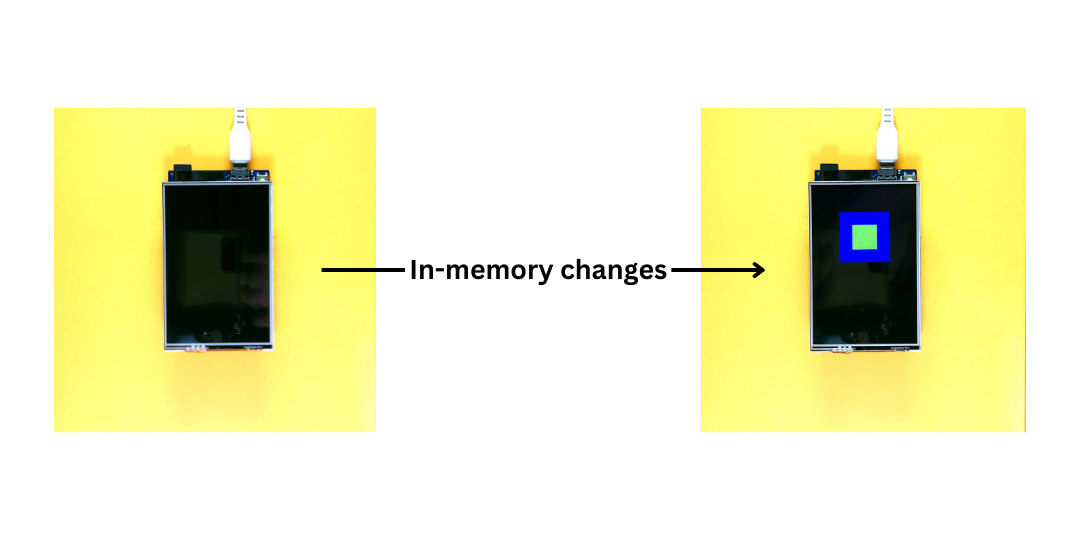
Displays are of two types, i.e. buffered and non-buffered. Buffering refers to storing a copy of the display's state, and reading from/writing to this copy instead of the real display. Every so often, the contents of the buffer are copied to the display. This can be done at fixed time intervals or after a certain number of changes have been performed.
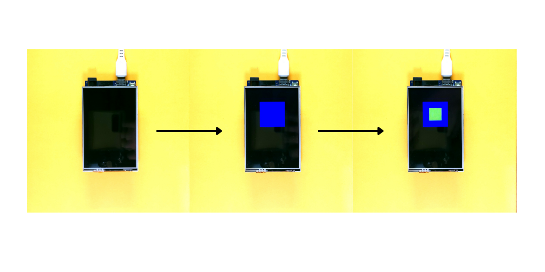
Buffering has the advantage of removing flickering caused by intermediate changes. For example, think of a rectangle with a thick border. Let the color of the border be B while that of the interior be C. One possible way to draw this, is to first draw an outer rectangle that is filled with the color B. Then, a smaller rectangle is drawn within this and filled with the color C. Without buffering, the pixels within the interior of the rectangle are updated twice (first with color B, and then C). This is not instant, and is perceived as a flicker. If a buffer is used, then the rectangles are first drawn onto the buffer and the buffer is copied to the display. This way, each pixel is updated only once, with its corresponding value in the buffer, thereby removing all flicker.
Buffering can be done using software or hardware. In the former case, a software library must be responsible for making all changes to a buffer and then providing a special function to transfer the changes to the real display. In the latter case, the driver must implement the buffer and provide a special command to transfer the changes to the real display. The ILI9486 driver does not provide buffering, and therefore it must be done in software (if at all).
However, buffering has a cost. It needs a proportionate amount of memory, which is generally not available on microcontrollers, and is expensive to add to display drivers. A 480x320 display with 16-bit color depth requires 307.2 KB to store. To put that into perspective, the Arduino UNO R4 has 128 KB of program storage and 32 KB of memory, while the Arduino UNO R3 has 32 KB of program storage and 2 KB of memory.
Something to note, however, is that it is not necessary to always buffer the entire display. This can be the case when a majority of the screen is used to show a static image. An example could be a game where the player controls a space-shuttle, where the bottom half of the screen is used to display the controls of the shuttle and only the top-half shows a dynamic scene. In such cases, it may be feasible to store the buffer in memory, depending on the size of the region.
The code provided in this series does not use display buffering.
Introducing the Adafruit GFX & MCUFRIEND libraries
To manage graphics and communication with the display, this blog uses the Adafruit GFX and MCUFRIEND libraries respectively. Note that we will be using a fork of the MCUFRIEND library, as the original only supports AVR Boards (the UNO R4 Minima and WiFi are Renesas Boards). The fork maintains compatibility with AVR Boards and adds support for the UNO R4 series.
The Adafruit GFX library provides the Adafruit_GFX class, which acts as a super-class for various displays. It provides functions to handle many kinds of drawing, such as lines, rectangles, circles, custom bitmaps, text etc. It also provides functions to set the rotation and color-inversion of the display. It requires only the drawPixel method to be implemented by the child-class (at the minimum) for its other methods to work. The child-class can, if needed, override other methods (if the hardware natively supports them) to speed things up.
For example, consider the drawRect method in Adafruit_GFX. This method has a default implementation which relies on the drawLinemethod. The drawLine method in-turn relies on the drawPixel method to do its job. If a display driver natively supports drawing lines, then the drawLine method can be overridden to directly use this command instead of the drawPixel method (which must be implemented anyways). This will speed up the drawLine method and any other methods that rely on it, such as the aforementioned drawRect method.
Using this technique, different displays (having different resolutions, drivers, colors) can use the same library, and be controlled with the same set of methods, whilst still working close to their native speed.
The Adafruit GFX library also provides other classes to make it easier to port different displays, but those are not used in this blog.
The MCUFRIEND_kbv library provides the MCUFRIEND_kbv class, which is a specialization of the Adafruit_GFX class for communicating with various displays. The following snippet shows its usage -
First, an object of the MCUFRIEND_kbv class is created in the global scope. This object is initialized using the begin method, which also accepts the ID of the controller used as an integer (conventionally specified in hex notation). For a complete list of supported values, seehttps://github.com/prenticedavid/MCUFRIEND_kbv/blob/master/MCUFRIEND_kbv.cpp.
The MCUFRIEND library is created to work with many controllers, of which the ILI9486 is just one. For example, If you were using the ILI9431 controller, you would specify 0x9431 instead.
Installation and detailed usage is shown in the next section.
Introducing the Adafruit Touchscreen library
To communicate with the touchscreen, this blog uses the Adafruit Touchscreen library. This library provides two classes, TouchScreenand TSPoint. The low-level IO required to get touch coordinates is handled by this library.
The readings provided, however, are raw, i.e. they are not suitable for use in applications. To make these usable, a calibration step is performed, where we get the positions of a few known locations on the display (usually the corners). These values are then used in all future programs to convert the raw readings to coordinates on the display.
Installation and detailed usage is shown in the next section.
Code for using ILI9486 TFT LCD shield with Arduino
This section shows how to program the Arduino to operate the display. After completing this section, you should be able to write your own programs to draw various objects on the display.
Installing the libraries
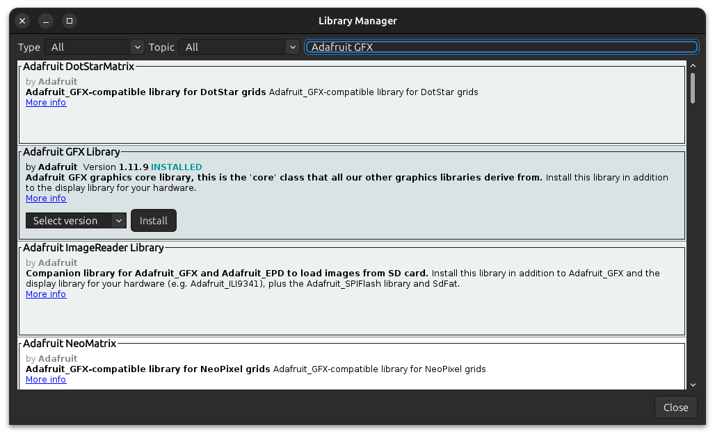
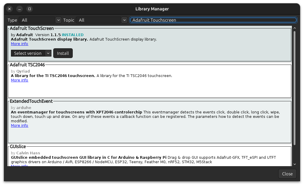
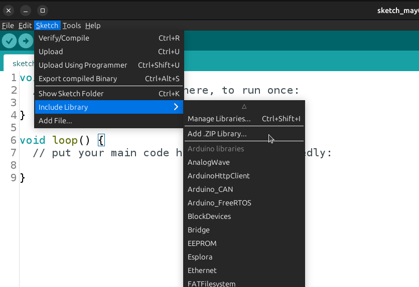
First, it is necessary to install the libraries mentioned in the previous section. The Adafruit GFX and Adafruit Touchscreen Libraries can be installed simply from the Library Manager in the Arduino IDE.
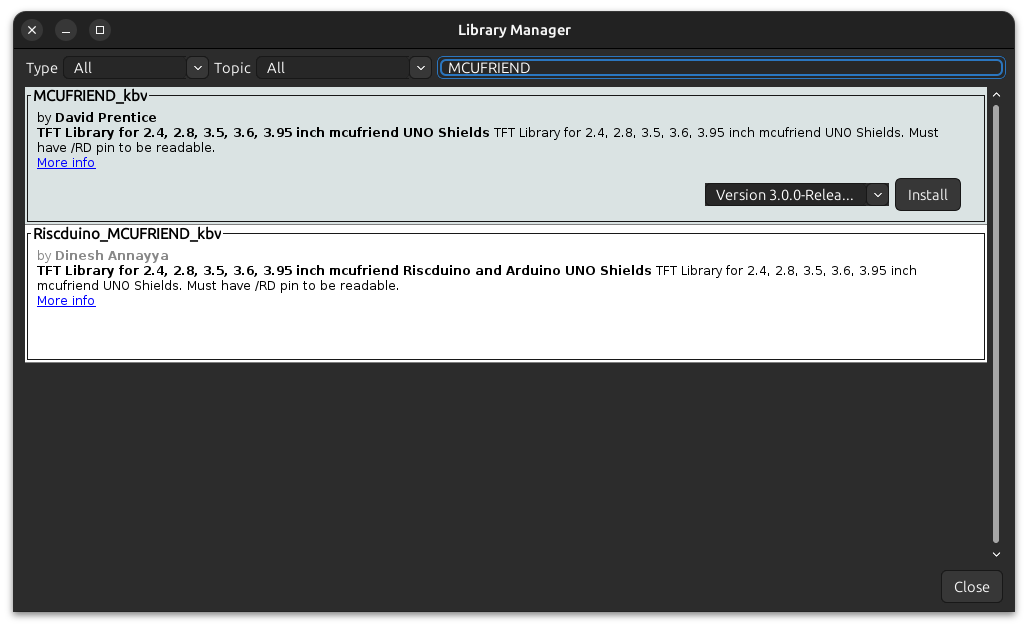
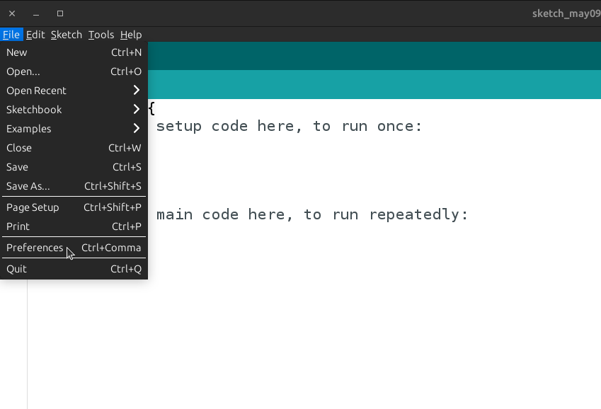
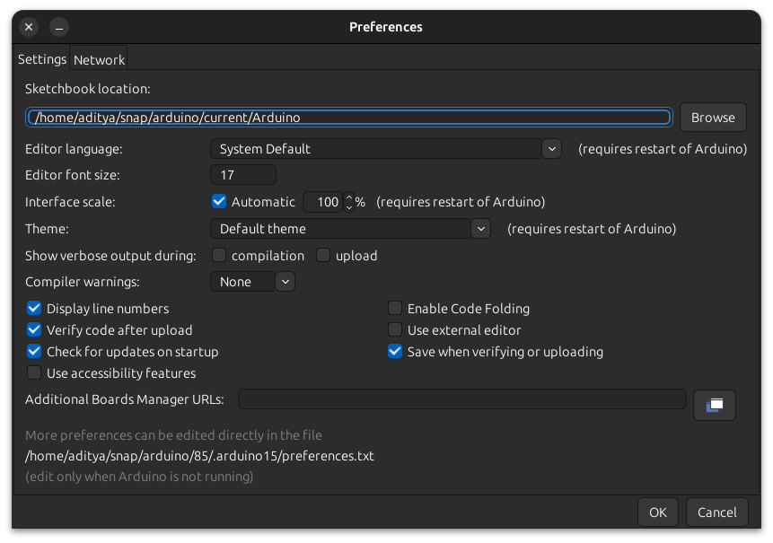
The MCUFRIEND library, however, should not be installed from the library manager. This is because the default version is not compatible with the Arduino UNO R4 Minima and Arduino UNO R4 WiFi. Consequently, we have to use a fork of it. The first step is to go to the Arduino IDE and find your library path, i.e. where the Arduino IDE stores all installed libraries. This can be done by going to "File" > "Preferences", or by using the keyboard shortcut "Ctrl + ," ("Cmd + ," on Mac). Find the box labelled sketchbook location, and copy the path given within it. Next, open this repository in your browser. From here, there are two ways to proceed.The MCUFRIEND library, however, should not be installed from the library manager. This is because the default version is not compatible with the Arduino UNO R4 Minima and Arduino UNO R4 WiFi. Consequently, we have to use a fork of it.
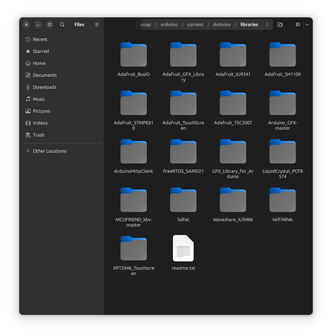
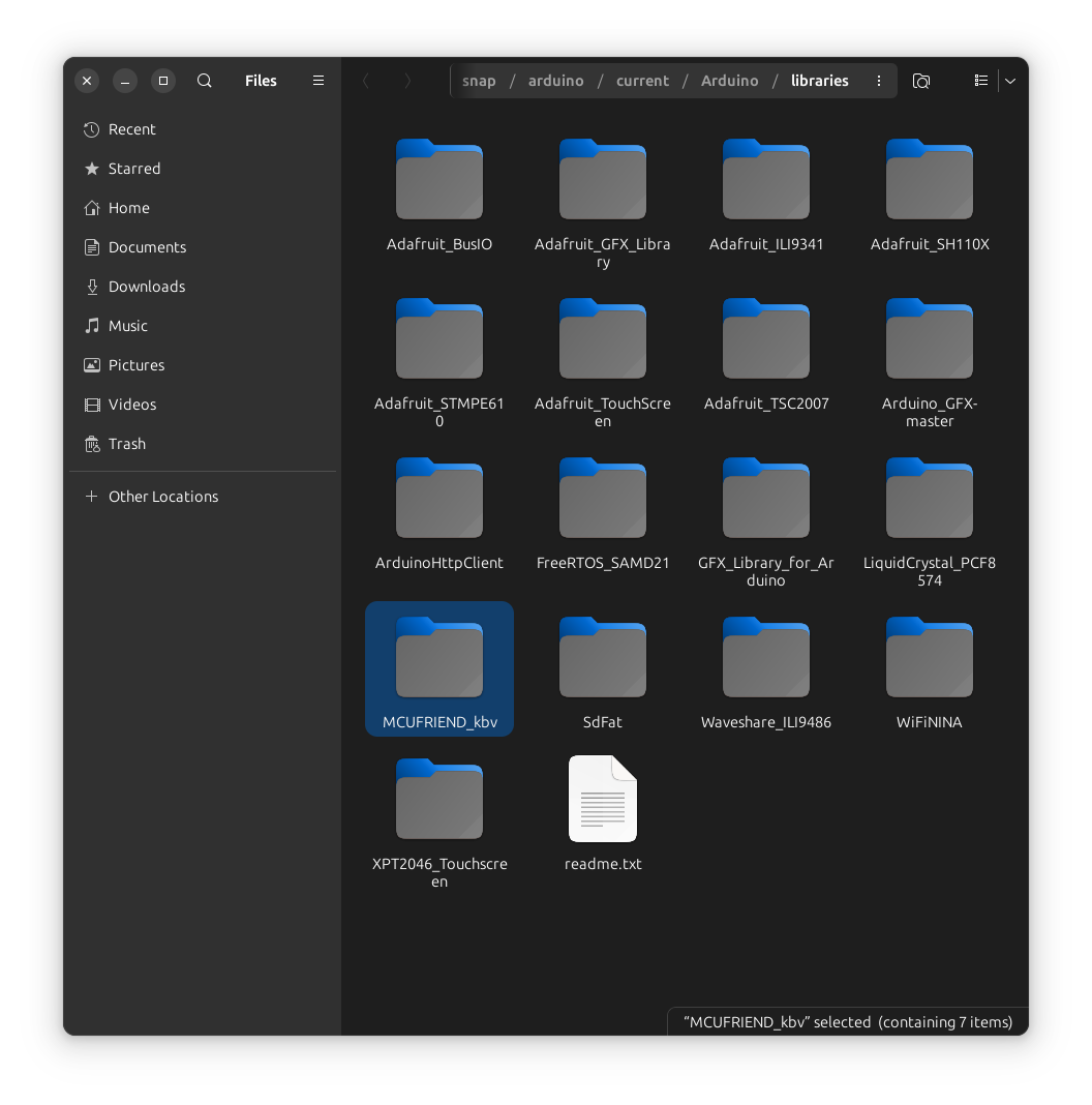
If you are comfortable using git on the command-line, you can open the sketchbook directory and cd into the libraries directory present in it. After this, you can clone the repository into this directory, and restart the Arduino IDE. The library should become available in your library manager, as well as in "File" > "Examples".
If you do not have git installed, you can download the repository from Github as a ZIP File. Then, navigate to the sketchbook location (click the browse button next to the box) and go into the librariesfolder. Extract the ZIP file into this location, and rename the extracted folder to MCUFRIEND.
If you are using PlatformIO, you can add the URL of the repository to the lib_deps section in the platformio.ino file.
The SD Card library is included with the Arduino IDE/Arduino CLI/PlatformIO installation. In the rare case that it isn't, you can install it from the library manager.
This concludes the installation of the libraries.
Running an example from the library on the TFT LCD shield
Starting out, it is a good idea to run some of the examples included with the library. These examples are known to work, which allows any problems that pop-up to be easily narrowed down to the hardware setup.
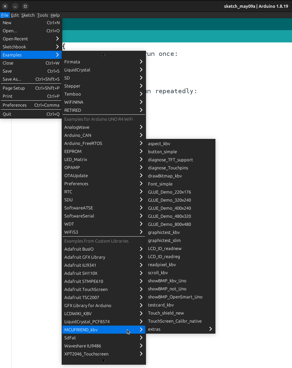
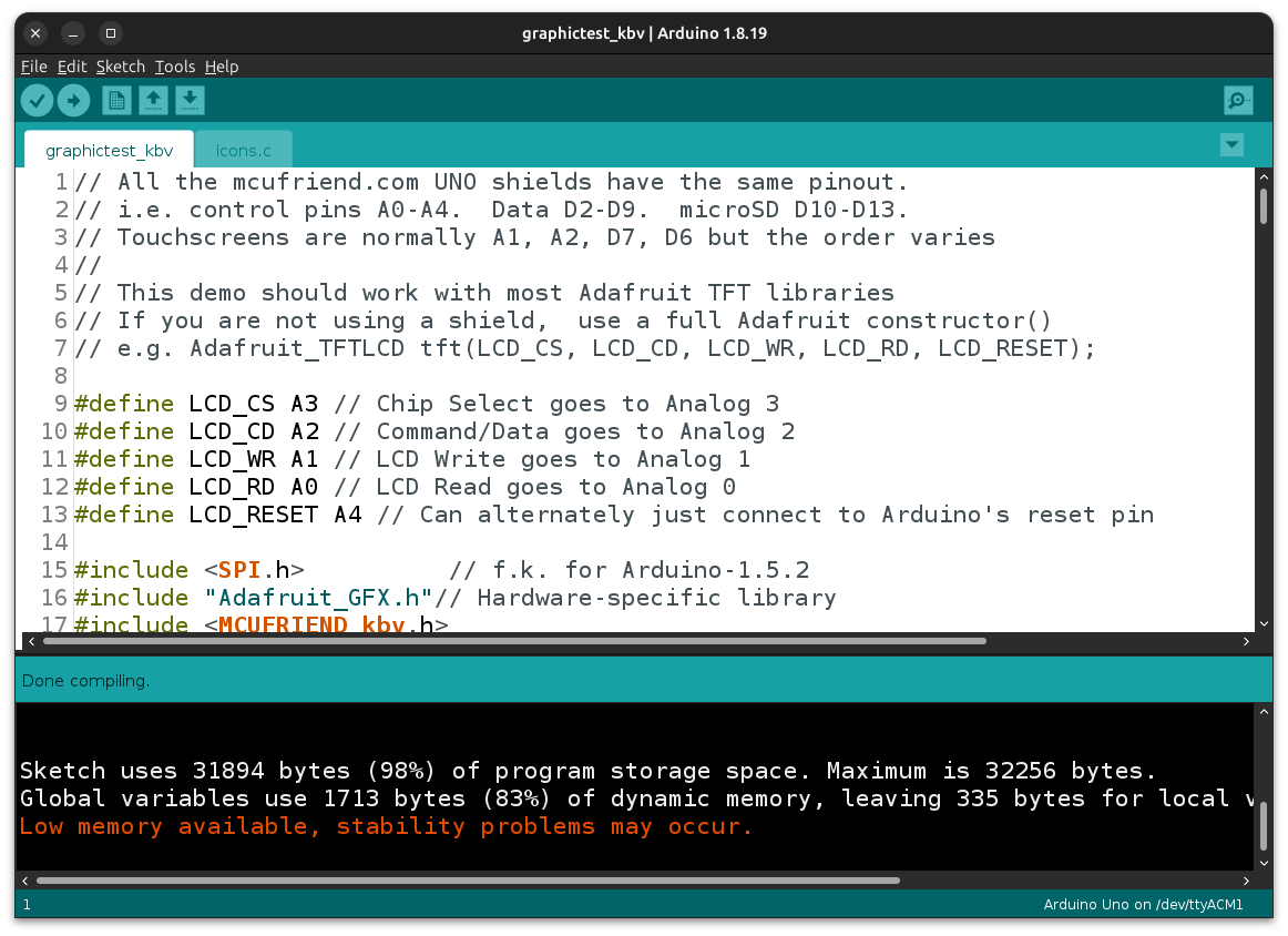
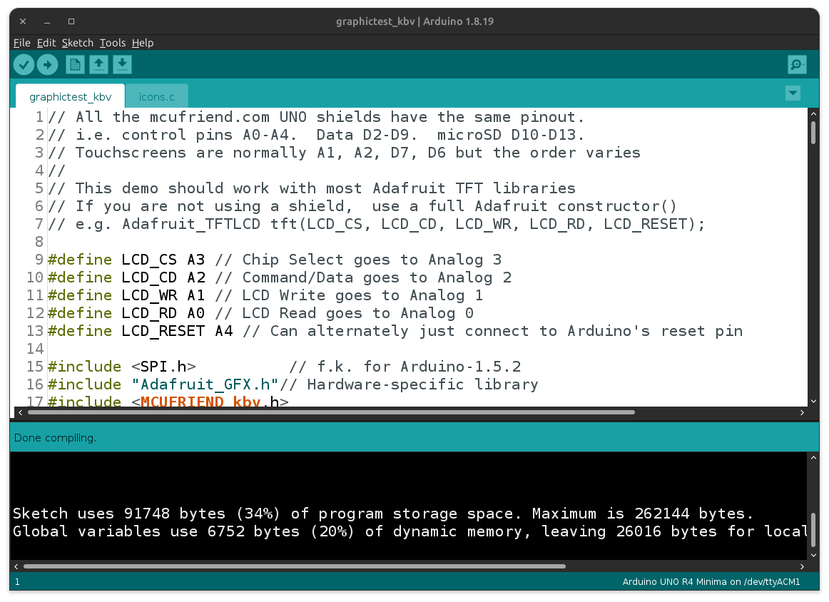
To test the display, open "File" > "Examples" > "MCUFRIEND_kbv" > "graphicstest_kbv", which is a comprehensive test of the complete features of the display and library. Interestingly, it uses up almost the entire storage available on the Arduino UNO R3 and requires a lot of space even on the Arduino UNO R4.
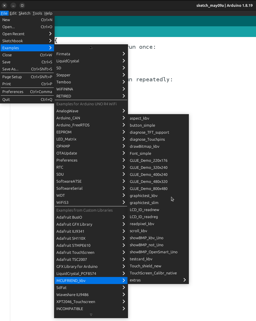
By default, the example reads the ID of the display and uses this value to initialize it. But since we already know that the display uses an ILI9486 driver, we can force it to use this value directly by modifying the setup function as shown below -
This is the same as the setup function in the snippet shown earlier in this blog, which showed how to use the MCUFRIEND Library. Plug your shield into your Arduino UNO and upload this program to it. If there are no problems, you should see the following -
- The screen should cycle through solid color backgrounds.
- Some text is printed in the top-left corner in different colors and sizes
- Diagonal lines of the same color are drawn originating from each of the corners and spread out in each direction.
- Horizontal and vertical Lines are drawn in various colors.
- Hollow rectangles are drawn.
- Filled rectangles are drawn.
- Hollow circles are drawn.
- Filled circles are drawn.
- Hollow triangles are drawn.
- Filled triangles are drawn.
- Hollow rounded rectangles are drawn.
- Filled rounded rectangles are drawn.
- The amount of time taken for each of the above are printed in green in the top-left corner of the screen as performance information.
- Some text, a bitmap and a color gradient are shown on the screen. A part of this text is scrolled horizontally and vertically. This process is repeated once for each rotation (portrait, landscape, inverted portrait, inverted landscape). This entire process is itself repeated after inverting the color.
Writing your first program from scratch to show colors
While the example was useful to test if the setup works, it is a rather complicated program. Therefore it helps to write a minimumprogram to understand how to use the library, i.e. a program with only the bare-minimum functionality (and size) for it to work. Consider the following code -
This program defines aliases for some commonly used colors, and draws pixels of the color red, green, blue and yellow in the clockwise direction, near the corners of the display. It reveals some important facts -
- The origin of the coordinate system is in the top-left of the display.
- The first coordinate that is specified in methods is in the horizontal axis, or the x-axis. This value denotes the offset from the left-edge of the display.
- The second coordinate that is specified in methods is in the vertical axis. This value denotes the offset from the top-edge of the display.
- The colors are specified as 16-bit unsigned integers, of the form
rrrr rggg gggb bbbb. By convention, the representation includes 4 nibbles of 4 bits each. The first 5 bits are used to mark the intensity of the color blue, the next 6 for green and the next 5 for red.
The encoding scheme of the colors may not be very intuitive from the get-go, but becomes very clear when you represent the number as rrrrr gggggg bbbbb instead of rrrr rggg gggb bbbb , The intensity of each of the colors/channels is individually stored in their respective bit-fields. The intensities of the red and blue channels is a number between 0 (0%) and 31 (100%), while that of the green channel is a number between 0 (0%) and 63 (100%). This does not mean that the green has a higher total intensity, only that it has a higher resolution, i.e. the same range of 0% to 100% can be broken down into more discrete values.
Working with colors
If you wish to convert a color from 24-bit (which is a more conventional format) to the 5-6-5 format, see the following function (written in python) -
This converts colors of the form (R, G, B), where each is a number between 0 and 256 (exclusive), to a format understood by the display and library. If you call the function with arguments r=255,g=0,b=0 then the output comes out to 0xf800, which matches up with the definition of the constant RED in the previous example. You can use these to create your own definitions. If you wish to blend 2 colors in a known ratio, you can use the following python function -
This function expects two colors (in 16-bit form) and a percentage value D. It blends the two colors C1 and C2 in the ratio D:(100 - D) and returns the result in 16-bit form. It does this by isolating all three channels from both of the colors and taking a weighted mean. The values are then combined back into a new color which is returned. Both of these functions can also be written in C++ for the Arduino to execute. Here is how it would look -
Note the use of the constexpr keyword before the function definition. This has been used for performance reasons, as it forces the compiler to execute the function at compile-time wherever possible (it may not always be the case that the value can be calculated at compile-time). If the arguments (colors) provided to the function were known at compile-time, then this function will always be evaluated at compile-time and the resultant color would be used directly by the caller when the program is actually executed on the Arduino.
A simple program to use the touchscreen
The following code snippet introduces a basic program to read and display raw readings.
The first part of this program includes the Adafruit Touchscreen library, creates aliases for the pins used by the touchscreen and defines the PRESSURE_LO and PRESSURE_HI constants, which denote the range of pressure for a touch to be considered valid. These are not in any particular unit, and are simply based on observations.
Next, it creates an object called ts of type TouchScreen, which is responsible for communicating with the touchscreen. The arguments to the constructor are the GPIO pins which the touchscreen is connected to as well as the resistance across the x-plate. You can leave these values as is.
The program defines 2 functions apart from the standard setup and loop functions given by Arduino -
to_display_mode- As mentioned in the first section of this blog, the touchscreen and ILI9486 IC share the same physical pins. When the touchscreen library is used to read the screen, it changes some of the pins to be inputs. This function sets them back, i.e. changes them to outputs, allowing them to be used for sending signals to the display controller. If this function is not called after the touchscreen is used, then the MCUFRIEND library will start causing unexpected behavior.get_touch- This function simply reads the screen in a loop till a valid touch occurs. When one does occur, its details are transferred from the TSPoint object to variables whose pointers are passed as arguments to the function.
The get_touch function is called in the loop and its readings are printed. You can also modify the program to print the pressure to see how it changes as you press with more or less force.
The uint16_t type is used for tx and ty to remove ambiguity regarding the size and signed-ness of the values. This way, it is known that the values will lie between 0 and 65,536 (exclusive), which is enough for our purpose. If int were used instead, the values could have been negative, which represents an invalid state.
The program to calibrate the touchscreen is given in the next part of this series.
Final Thoughts
Getting the individual components of the ILI9486 TFT LCD Shield to work with the Arduino UNO was a detailed process (especially with the UNO R4), from finding the right libraries and understanding their architecture, to calibrating the touchscreen. This blog (and series) is an effort to consolidate this scattered information in one place for easy comprehension.
By the end of this blog, you should be comfortable with the basics of programming the ILI9486 touchscreen shield with the Arduino. This includes understanding the role of libraries, handling color encoding, and dealing with raw touch data. I hope that you were able to follow along and try out the demonstrations given in this blog yourself. If you have any questions or suggestions, feel free to drop them in the comments below!
The next parts of this series (click here) delve deeper into touch calibration, SD Card storage and building complex applications such as Paint and Tic-Tac-Toe.