Understanding and Reading Circuit schematics for Beginners
By Aditya
/
October 18, 2019
Circuits can be represented in many different ways, from a realistic pictorial view, to a block view (A flowchart explaining the working of the circuit). In this guide/tutorial, I will be explaining how to read, understand, interpret and even make your own schematics as an absolute beginner who may not be ready to read advanced tutorials yet. Let's get started!
Why go schematic, are there significant advantages?
Circuit schematics are, by far, the simplest way to show a circuit whilst also not compromising on details. The diagrams of parts used are also quite standard across the world, which means that your circuit will be simple to draw and will be readable around the globe (barring a few minor differences between countries).
Drawing a pictorial representation of the circuit (realistic view) might help to get a feel for the shape and size of the components, but will be tedious and time consuming (picking components of the right size can also be done after the circuit has been designed). A circuit could also be drawn informally, i.e. with your own representation, but this would only be readable by yourself, not others. Schematic representations of circuits takes care of both these problems.
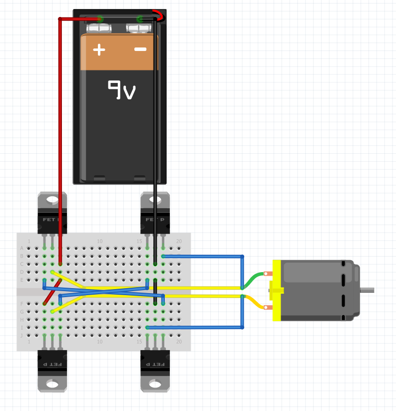
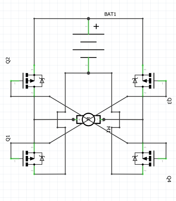
The difference can be seen in the above two images that represent the same circuit.
Some common symbols
Before proceeding any further, it is essential to get familiar with a few basic components in schematic view -
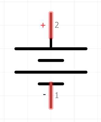
This is the symbol for a generic DC source. It consists of a pair or multiple pairs of parallel lines, with the shorter one indicating the cathode (ground) and longer one indicating the anode (VCC). Each pair indicates a single cell of a particular voltage. It is the power source of your circuit.
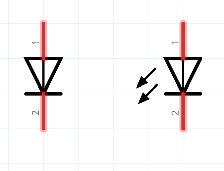
Next, comes the diode and LED (Light emitting diode). It consists of an arrow with a bar on one side. The bar indicates that current can only flow towards the tip of the arrow and not the other way round.
The symbol for the LED is the same, with the additions of either two or three small arrows drawn diagonally on the side (to represent the emission of light).
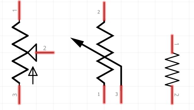
The resistor is simply a zigzag line with the resistance written beside it (usually in ohms). The rightmost one is a common resistor while the other two are variable resistors or potentiometers (POTs for short). The pots have a third line either crossing or touching the main resistor, indicating a movable knob or slider.
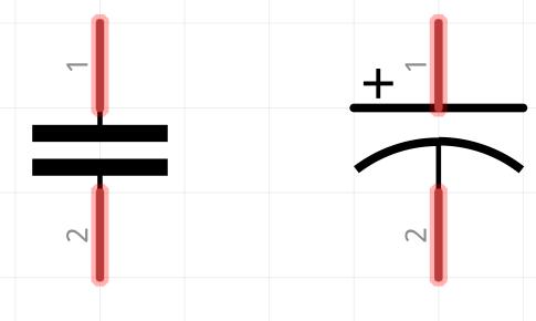
Capacitors are similar to batteries, except they contain only a single pair of lines of equal length. A ceramic capacitor (not polarized, shown on the left) has both the lines straight while an electrolytic capacitor (polarized, shown on right) has the cathode as a curved line while the anode is straight. The capacitance is written beside in farads.
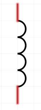
The Inductor looks similar to a resistor, but with curved lines. The inductance is written beside in henry. It is can be used to filter AC current or to store energy similar to a capacitor. The difference between an inductor being that the capacitor stores electrical energy in the form of an electric field while a capacitor stores it in the form of a magnetic field.
Lastly, come transistors. BJTs are shown on top (PNP on left, NPN on right) while MOSFETs are shown below (N channel on left, P channel on right). Transistors can be thought of like switches, but rather than being opened/closed mechanically, they are controlled by using a separate electric current/voltage.
The operation of BJTs are controlled by current and those of MOSFETs are controlled by voltage.
*Note- There are A LOT of components out there and it is not possible to show the name and schematic representation of every component. If a component is found that is not in the above list, google is your best friend.
Junctions and jumps
When drawing a schematic, it might occasionally get difficult to determine if a pair of overlapping wires are connected or not. To solve this issue, jumps and junctions are used.
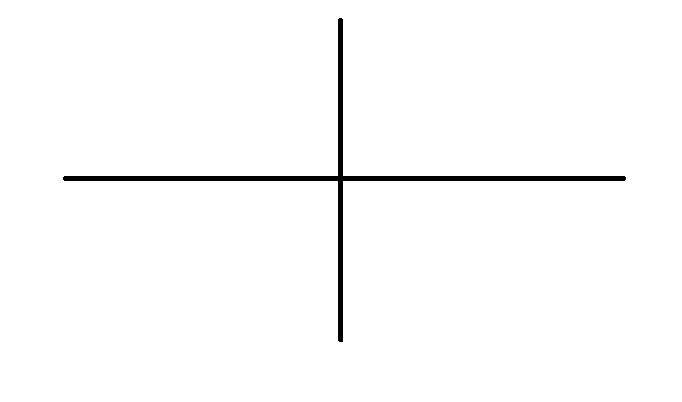
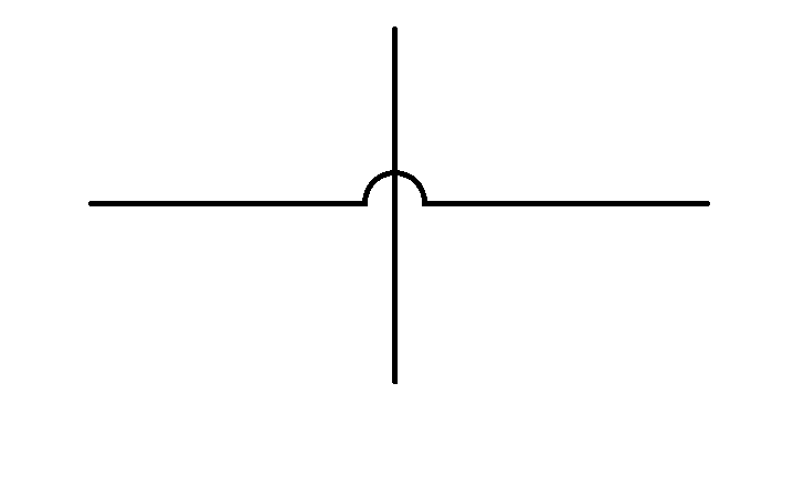
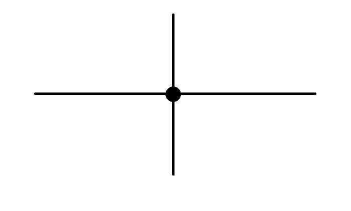
In the first diagram, the wires are simply crossing over and it is not quite clear if they are connected or not. In the second diagram, however, it is clear that the two pairs of wires are not connected because of the explicit jump used between them. The connection is also clear in the third diagram due to the blot used to represent the junction.
A jump is simply a curved line/arc in a wire to indicate that it is not connected to the wire it passes over. A junction is a thick dot or blot over a pair (or more) of wires to indicate a connection between them.
Drawing a schematic
To start drawing in schematic view, you must either have the circuit ready in front of you or you must be familiar with the circuit. The schematic can be drawn by hand or via software (I have used Fritzing).
Start by placing the power source and then the components each one by one but don't start connecting them as this can cause confusion later down the line, especially in larger circuits.
In this example, I am going to show how to design a simple 3x3 button matrix.
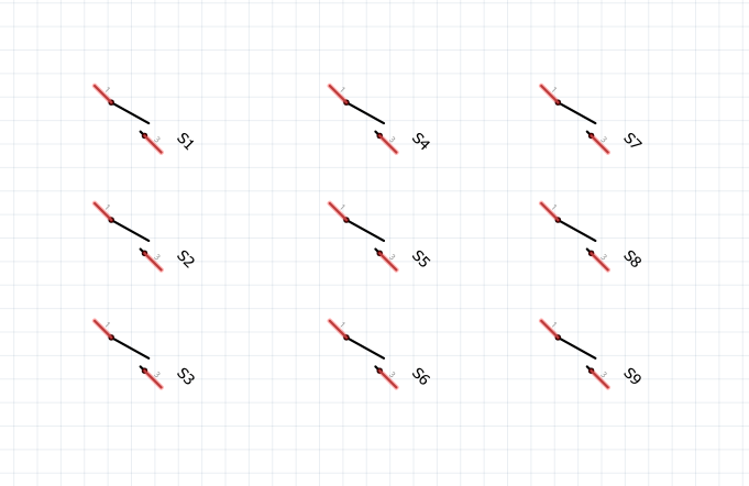
Here are the nine pushbuttons, each rotated 45 degrees clockwise. I have drawn all the buttons before starting the connections because I don't want to find out later that I their is a wire where a button needs to go, because while the wire can be moved without changing the looks of the circuit much, the buttons are bigger and can cause the same circuit to look more confusing.
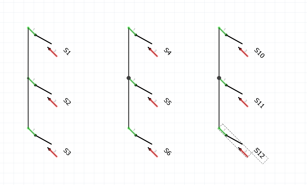
Next, the rows are connected together.
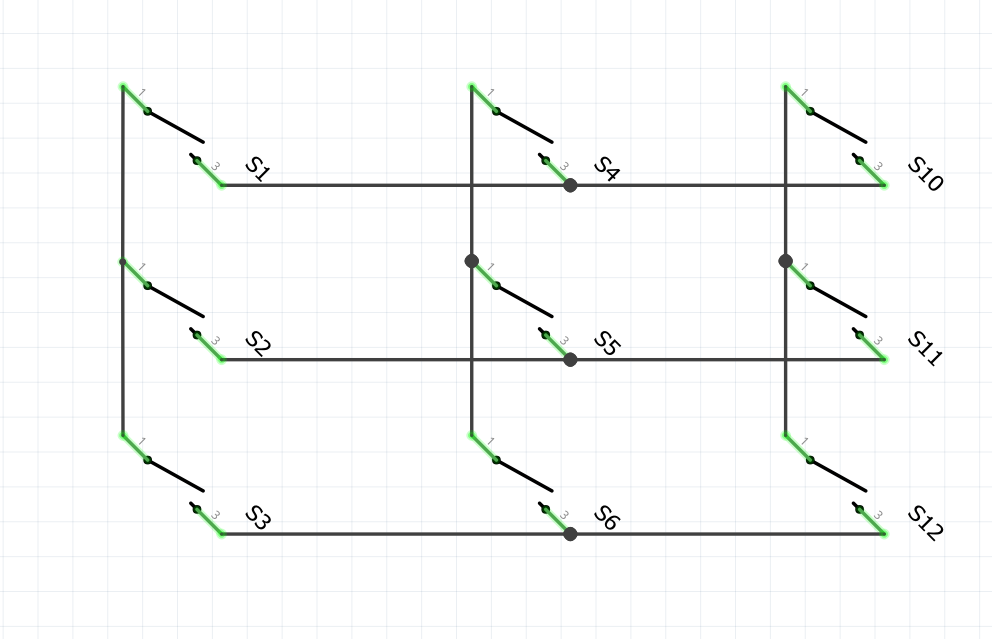
Finally, the columns are connected together, and the circuit is complete. Here is the pictorial representation of the same circuit -
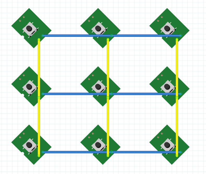
You can see the difference for yourself.
Additional Resources
Now that you have finished reading this tutorial, I recommend that you go through the following tutorials as well to help you get a better understanding of the subject as well as practice to make sure you are all clear.