Programming Arduino and AVR Microcontrollers using the Assembly Language
By Aditya
/
July 31, 2022
In this blog, I will be explaining how to get started with bare-metal Assembly Language programming on AVR microcontrollers, along with an example for the ATmega328P. We will see how a program is stored and executed by the Microcontroller's hardware; the syntax of the Assembly language, and also how to build and upload your program using the toolchain provided by Atmel/Microchip. We will put it all together with an example program to blink an LED.
This is a long blog because, unlike several other tutorials that cover some aspect or the other (and do it well), the attempt in this one is to take you through the complete journey from the very basics of assembly language to writing a working example, building it and seeing it run on your setup. The blog has been divided into sections to help in selective reading as well.
You will get the most out of this blog, if you are familiar with C/C++ microcontroller programming, either within the Arduino ecosystem (Arduino IDE) or using the tool-chain that Atmel/Microchip provides (Atmel Studio).
Let's get started!
Program storage and execution in the AVR architecture
High-level languages (such as C/C++) provide you with constructs that your microcontroller does not inherently understand. While writing Assembly, however, you must deal with the hardware in a much more direct manner. Because of this, it helps to be aware of the hardware components inside an AVR microcontroller and the role some of them play in the storage, execution, and management of your program. Shown below is a block diagram of AVR microcontrollers.
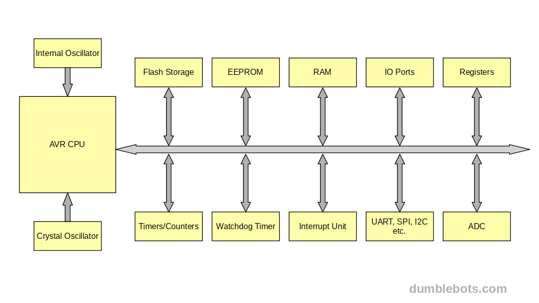
For the purpose of this blog, we will look at the Flash and SRAM in a little more detail with respect to the role they play in the execution of your program. If you wish to read more about the AVR architecture and its hardware components, then click here.
Flash (program storage)
The Flash memory of your microcontroller is where your program is stored. It is persistent, i.e. its contents are preserved even when the microcontroller is powered down. Each location in the flash has an address (usually written in hexadecimal notation), which is used when reading from or writing to the flash.
Since Instructions on the AVR architecture are encoded into either 2 or 4 bytes, the flash is "paged" into 2-byte pages while it is being accessed by any external hardware or when executing jump/branch operations. This means that when uploading programs to/reading a program from the microcontroller's flash, the smallest unit which can be accessed is a page and individual bytescan not be accessed this way. This implies that any string literals/arrays which are stored in the flash must have an even length (in bytes). If they are of an odd length, the assembler adds an extra byte (usually 0/NULL) at the end of it.
For example, if we want to write the string "Hello" to the flash, we would first have to modify the string to make its length even i.e. add an extra character at the end. In most cases, a NULL suffices ("Hello" becomes "Hello\x00"). Do not confuse this with the NULL byte added to the end of C/C++ strings. We then get the ASCII values of each of the characters, which are 0x48, 0x65, 0x6C, 0x6C, 0x6F, and 0x00 respectively. After this, each pair of characters would then be taken and written to the first available location in the following manner.
| Location | Low byte | High byte |
|---|---|---|
| 0x00 | 0x48 (H) | 0x65 (E) |
| 0x01 | 0x6C (L) | 0x6C (L) |
| 0x02 | 0x6F (O) | 0x00 (NULL) |
In a similar way to this, the instructions that make up your program are written to the flash in contiguous locations, starting from the address/location 0x00. This is where your microcontroller starts reading and executing instructions from when it is powered on.
At any given moment, the address of the instruction being executed is stored in the Program Counter (PC) register. A register is a hardware unit that stores a fixed length number as long as power is supplied to it. The Program Counter in AVR is 16 bits wide in most cases, and 22 bits wide on certain microcontrollers with bigger flash sizes. The Program Counter is also called the Instruction Pointer in some other architectures and they both mean the same thing. Note that the Program Counter also stores the address of a "page" instead of a byte.
Normally, the value in the PC register is incremented after executing the instruction it currently points to, which is typically once every clock cycle. Exceptions to this are when the current instruction is 4 bytes (2 pages) long or takes more than a single clock cycle to execute. Depending upon the case, it is either incremented more than once or not at all for that clock cycle. Furthermore, if a jump/branch is executed, the value in the PC register is updated accordingly. A jump/branch resumes the execution of the program from a specified address/location. The instruction which performs the jump/branch must also use page addresses rather than byte addresses.
A running program, however, when trying to read from/write to the flash, does not use page addressing, and instead uses byte addresses. For example, if a program running on the microcontroller were to read the string "Hello" (the one we previously wrote to the flash), it would access individual bytes in the following way.
| Location | Value |
|---|---|
| 0x00 | 0x84 (H) |
| 0x01 | 0x65 (E) |
| 0x02 | 0x6C (L) |
| 0x03 | 0x6C (L) |
| 0x04 | 0x65 (O) |
| 0x05 | 0x00 (NULL) |
The addresses shown above are of individual bytes rather than pages. Initially, the two addressing schemes might sound confusing, but consider why this was done. By paging the flash (for the program counter and any external hardware trying to access it), the number of read/write operations needed to be performed on it is cut by half, consequently, the speed of access is doubled. The Program Counter can also access double the number of locations, without needing to double its size. The program, however, when trying to read string literals, is better off operating on a single byte at a time (due to limited resources on the small chip).
As explained, the flash is where your program is stored and accessed from. We will explain how the program gets into the flash later when we talk about the build steps and toolchain for Assembly.
RAM (program memory)
Moving on from the flash, we have the RAM, where all your runtime data is stored while the program is executing. This is not persistent, i.e. its contents are erased when the microcontroller is powered down. It has a separate address space from the flash and is not paged, i.e. each byte in the RAM can be individually read from and written to.
It is usually divided into three sections, the general purpose registers, special function registers, and general purpose memory (SRAM).
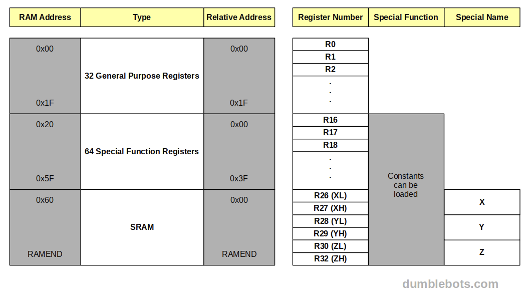
Each of these sections operates within the same address space and can be accessed using the same instructions. For example, a general purpose register can be accessed the same way any other location in the RAM might be accessed. However, this is not usually seen in practice, since optimized instructions exist for each of these sections. Let us take a closer look at them.
General purpose registers
The first part of the RAM are the general purpose registers which occupy the first 32 addresses (0x0000 to 0x001F). As stated earlier, registers are storage units of fixed length that are directly connected to the CPU. General purpose registers are 8 bits wide. For the CPU, data types and data structures do not exist. All data is stored in the RAM as bytes and to perform any kind of operation on this data, it must be copied (moved) into a register(s), operated on and then moved back out.
In Assembly programs, these registers can be referred to by their mnemonics R0 to R31. All 32 general purpose registers cannot perform all types of operations, i.e. certain operations can only be performed on some specific registers.
For those interested further,
- Constant values can only be loaded/moved into the last 16 registers (R16 to R31 inclusive).
- The register pairs R27:R26, R29:R28, and R31:R30 have reserved names (X, Y, and Z) which are used to store 16-bit addresses pointing to the RAM. They are also called pointer registers and have special instructions to operate on them.
- The Z register pair further has special instructions to increment/decrement it after loading the value it points to.
To perform any kind of arithmetic or logic operation on any kind of data, or to move data from one location in the RAM to another, it must first be moved into one or more of these registers. Only then can the data be operated on and/or moved to another location.
Accessing and operating on these registers is very fast, therefore, if your data can fully fit in the registers, it is recommended not to use the remaining RAM at all.
Special function registers
After the general purpose registers, the special function registers occupy the next 64 addresses (0x0020 to 0x005f). The Special Function Registers are also sometimes referenced by their relative addresses (0x0000 to 0x003F).
Like the general purpose registers, the special function registers are also 8 bits in size but are instead used to manage/check the state of the microcontroller and the program. Changing values in the special registers will affect the behavior of the hardware/running program in some way, such as enabling/disabling interrupts, enabling/disabling timers, changing the sleep mode, resetting the watchdog timer, etc. The values of certain special registers are also indirectly updated by the program, such as the negative and zero flags, which are set when the result of an arithmetic operation was negative or zero respectively. The values within these registers can be read by the program to find out the state of the microcontroller.
A subset of the special function registers are the IO registers. IO registers are also called IO ports, and both will be used interchangeably in this blog. Changing the value of an IO port causes a physical change in the state of the physical pins of the microcontroller.
Each physical pin requires 3 bits to completely manage its state. One bit controls whether the pin is an input or output, another bit controls whether the pin is set to high or low and one final bit is required to store the state of a pin when it is an input. A collection of 8 pins, therefore, requires 24 bits (or 3 bytes) to control. Therefore, the IO ports are divided into three types based on their function.
- Data Direction Ports (labeled as DDRA, DDRB, etc.)
- Digital Output Ports (labeled as PORTA, PORTB, etc.)
- Digital Input Ports (labeled as PINA, PINB, etc.)
Each bit of every port affects a single pin (some bits of some ports might be unused). Setting a bit in a Data Direction Port would put its corresponding pin in output mode and clearing the same would put the pin in input mode. Setting a bit in a Digital Output Port would set its corresponding pin to a high value and clearing the bit would set the pin to a low value, if the pin is in output mode. If the pin is in input mode, setting/clearing the same bit enables/disables the built-in pullup resistor on the pin. When a pin is in input mode, its corresponding Digital Input bit can be read to get the state of the pin.
Shown below is a table that summarizes this behavior, i.e. the state of a given pin and the state of its corresponding bits in the Data Direction and Digital Output ports.
| Pin state | Corresponding DDR bit | Corresponding PORT bit |
|---|---|---|
| Floating input | 0 (cleared) | 0 (cleared) |
| Input pullup | 0 (cleared) | 1 (set) |
| LOW output | 1 (set) | 0 (cleared) |
| HIGH output | 1 (set) | 1 (set) |
The registers should not be used by the program for storing/operating on values.
General purpose memory (SRAM)
After the general purpose and special function registers, resides the general purpose memory of an AVR microcontroller. It is used by the program to store its variables, arrays, objects, etc. typically in the form of a stack. A stack in the real world is a collection, where new items are added and old items are removed from the front only. The program's stack is similar to this. Whenever a function is called, it sets up a new stack frame, whose size is the combined size of all of its variables and objects. If this function in turn calls another function, the new function sets up its own stack frame on top of the current one, and this can repeat as long as there is enough memory available. When a function is done executing, its stack frame is freed, so that it can be used by another function (usually the caller).
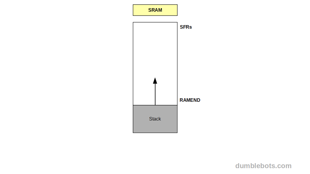
In AVR microcontrollers, the stack starts from the RAMEND (highest address) and grows towards the lower addresses (towards the Special Function Registers).
There are two special registers that keep track of the current function's stack frame, namely the "SPL" (Stack Pointer Low) and "SPH" (Stack Pointer High) registers. These are collectively called the Stack Pointer and point to the end of the current stack frame. Two registers need to be used because RAM addresses are 2 bytes long on AVR microcontrollers and the low and high bytes need to be stored in separate registers. For example, on the ATmega328P, the value of RAMEND is 0x08FF (2303 in decimal, which matches the 2K bytes of SRAM given in the datasheet). In this case, the initial value of the SPL register should be 0xFF, and that of the SPH register should be 0x08.
Fuses
Fuses are helpful to know about (especially for debugging) but are not essential for getting your programs to work, so you can skip this section for now and come back to it later.
Every AVR microcontroller includes what are called fuses/fuse bits/configuration bits. These are not the fuses you are used to (which are used to stop too much current from flowing through the system), but can rather be thought of as a special set of registers (even more special than all the other registers we have already talked about). They cannot be affected by the program and can only be changed by the use of an external programmer. Note that the word "programmer", as used here, does not refer to the person who writes the program, but rather to the device which transfers the program from your PC to the microcontroller's flash. We will talk about this in more detail in the coming sections.
The Fuse Bits store information about the microcontroller such as its clock frequency, clock prescaler, debugging, etc. Usually, fuse bits do not have to be altered for proper functioning but sometimes, they can cause very pesky bugs that are hard to debug, For example, your delay subroutines may be written assuming the clock to be 16 MHz (which is the default for an Arduino UNO), but if the "CKDIV8" bit is set in the fuse bits, then the clock is divided by 8 and all your delay subroutines will produce 8 times the expected delay. If your program seemingly has no bug but is still not behaving the expected way, it can be useful to read and check the values in the fuse bits of the microcontroller.
Reading and decoding the information within the fuse bits is not so straightforward. Here is a fuse bit calculator for AVR microcontrollers. You can input your microcontroller's current fuse configuration (obtained using a tool like Avrdude) into the calculator to derive their meaning.
Now that we have covered some of the important hardware components of an AVR microcontroller, let us get started with writing a program in Assembly and then get to building and flashing it.
Starting out with the Assembly language
In this section, we will first see a mini tutorial/overview of the Assembly language and gradually go deeper into it. Then we will write the popular blink example program for the ATmega328P. You can use any other AVR microcontroller too, as long as you make sure to use the correct pins and ports.
Introduction to Assembly and instructions
Let's start by considering the CPU inside your microcontroller. This executes the code that you write in any high-level language. A microcontroller always has a fixed set of instructions which it is wired for. Hence, all code has to somehow be translated to these instructions.
Broadly speaking, a program is a sequence of these instructions which gets executed on being run (usually one at a time). Each of these instructions is elementary in nature and performs a very specific task, such as moving a byte from one location in the memory to another, or adding two bytes and storing the result. Each Instruction has its own opcode, a fixed length number (usually written in binary or hex) that represents/encodes the instruction, along with any operands it might accept.
While theoretically, one could use only these instructions (their opcodes) to craft a program, it is time-consuming and error-prone in real life, not to mention the cumbersome work of remembering the opcodes of each variation of each instruction!
The Assembly language is a mnemonic, or set of symbols, which are used to represent these instructions in a human-readable language, along with directives for the Assembly process itself (more on this in the very next section). Since Assembly language instructions have a 1-1 correspondence with your CPU instructions (there are very few exceptions to this, but those will not be covered in this blog), any program composed in it is microcontroller dependent. What this means is that a program written for the ATmega328P will not normally work on another microcontroller, such as the ATtiny85.
The Assembly language also lacks the program constructs you are probably used to using such as data types, variables, functions, classes, and control structures (like loops, if-else, and switch-case to name a few) because your CPU does not inherently understand them either. You must instead interact with your memory and hardware in a more direct manner and achieve program flow control using logical comparisons, labels, and jumps (explained in the next section). Let us see what these are, along with the detailed syntax of the Assembly language.
Assembly syntax and constituents
An Assembly program is written as a sequence of instructions on separate lines, as shown below.
Each line contains a single instruction, followed by its comma-separated operand(s) (if any), followed by an optional remark/comment. Before covering instructions in-depth, it is helpful to have a look at what any programming language allows you to do. Broadly speaking, any Turing complete programming language must provide you with constructs to do the following.
- Perform Arithmetic (+, -, *, /, MOD, etc.) and Logic operations (comparisons) on data. (Type I)
- Jump and Branch to different parts of the program (whether it be conditional or unconditional). (Type II)
- Move around data in memory. (Type III)
- Control other peripherals (for example ports, timers, etc.) (Type IV)
As an example, consider a program that should add the numbers 2 and 3, and print whether the result is odd or even, to the console. A rough algorithm describing this program (along with the type of each step) is shown below.
- Let A = 2 (Type III)
- Let B = 3 (Type III)
- Let C = A + B (Types I & III)
- If C is odd, go to step 5 else go to step 6 (Types I & II)
- Print "odd" to the console then End (Type IV)
- Print "even" to the console then End (Type IV)
Since all high-level languages will allow you to implement the above algorithm, and all of them finally get translated to machine language instructions, the Assembly language also provides you with instructions to be able to execute the above operations.
An Assembly language implementation of the above algorithm snippet is given below. The numbers 2 and 3 are added, and then pin 1 on port B is set if the result is odd. Note that the below code is only a snippet, and a complete Assembly program requires more than just CPU instructions. You might only be able to understand the snippet partially for now (looking at the remarks and instruction names).
After instructions, assembly programs contain labels, which are user-defined symbols followed by a colon (:). They are case-sensitive. Labels are used to refer to the address of the line they precede. These can be used to find out the length of a particular sequence of instructions/bytes (by taking the difference between two labels/addresses) or jump to different parts of the code. Shown below is an example snippet of a loop that runs 5 times, implemented using labels.
Note that the underscore before the label names is put merely as a convention, to indicate that they are not subroutines and are just regular labels. Additionally, the label _loopend is only used to indicate the end of the loop and is not used by the program. The above code could have also been written as follows.
While the previous two snippets are exactly the same, the second one is formatted differently for readability with the labels in their own column. In the case of multiple files, a label can be made externally visible by writing .global <label-name>. Given below is the same snippet with the _loopstart and _loopend labels declared as global.
Apart from machine instructions, Assembly programs may also contain pseudo-instructions. These are not real CPU instructions, but only direct the Assembler during the assembly process. They are also known as Assembler Directives. The .global directive is one such Assembler Directive which we have already used.
Shown below is another example using labels and Assembler directives that places the string "Hello World" in the flash and stores its length in a symbolic constant. Each pair of characters is placed page-wise. Since the length of the string is odd, an extra NULL (0) byte is added at the end.
In the above snippet, .ASCII is not a real CPU instruction, but instead an Assembler Directive which tells the Assembler to place the specified ASCII string at that location. Any instructions that follow or precede it are preserved, with the 12-byte (11 bytes is rounded up) long string being stored in between. To refer to the string, the label MSG can be used.
The length of the string is also calculated and kept in the symbolic constant MSGLEN. Note that unlike MSG, MSGLEN is not a label. Henceforth, wherever the symbol MSGLEN appears in the program, the Assembler will do a blind replace with the value 12. The expression (MSGEND - MSG) is what is used to calculate the length of the string between two labels.
Finally, all Assembly programs are divided into sections (also called segments). A section is a relocatable unit of code. This means that the Assembler decides where each section will be placed within the RAM. All programs must contain three basic sections, which are .text, .bss and .data. Shown below is a completed program to add two numbers and switch on pin 1 on port B if the result is odd.
The .text section contains the program which is executed. The .bss section contains all uninitialized global variables/arrays and static variables. The .data section contains all constants and initialized variables. Your programs might also contain the.bootloader and .noinit sections, along with any number of application-defined sections, the discussion of which is beyond the scope of this blog.
Also note that different assemblers might give different names to these sections (along with having slightly different syntax and names for the assembler directives). For this blog, we will be using avr-as and you do not have to worry about different Assemblers for now.
To summarize, an assembly program contains -
| Instructions | Individual operations that are directly wired into the CPU for performing arithmetic, logic, jumps, etc. |
| Labels | Human readable references to locations within the program for managing flow, calculating length, etc. |
| Assembler directives | Directives to instruct the Assembler on the Assembly process such as making a symbol/label global. |
| Constants | Literal values embedded into the program. |
| Symbolic constants | To evaluate an expression once and substitute its value for the corresponding symbol everywhere in the program. |
| Sections/segments | The smallest unit of a program that can be relocated inside the flash (contains all the above). |
Blink example program in Assembly
In this section, we will see a tutorial on how write the popular blink example for the ATmega328P, where an LED connected to the microcontroller is blinked. On Arduino boards that use the ATmega328P (like the UNO), the built-in LED is controlled by pin 13. Note that the corresponding physical pin on the microcontroller is pin 19.
You can use any text editor to write the program and do not need an IDE (like Atmel Studio or Visual Studio) for this. You can name the file main.S. If you prefer any other name, make sure to substitute it in all the build commands. The ".S" extension, however, must be preserved case-sensitively.
We first include the avr/io.h header file, which contains preprocessor macros and aliases for all the pins, ports, special registers, etc. Without including this file, we would have to remember the exact addresses of all the above mentioned hardware units. We can use C/C++ preprocessor directives (such as #include, #define, etc.) normally in the program. After including the file, you can enter the boilerplate to define the three basic sections. Your code should look as follows.
The .org directive tells the assembler, the address from which to start placing instructions.
Setting the pin mode
We can now set the microcontroller's physical pin 19 as an output. Recall that this is pin 5 on port B, and we have to set the fifth bit in the DDRB register. There are several ways to achieve this. One way is to load the bitmask 0b00100000 into a general purpose register and then move it out to the DDRB register. Enter the following code after the .org directive.
The LDI (LoaD Immediate) instruction loads a constant/immediate value into a register. It only works for registers 16 to 31. PB5 is a macro that evaluates to 5. The expression (1<<PB5) (1 left-shifted 5 times) is evaluated at assembly time and has no runtime overhead. The Assembler simply replaces it with the value it evaluates to. You could have even directly written 0b00100000 (or 1<<5), which would have evaluated to the exact same machine code. Using the first approach, however, depicts the intent of the program with greater clarity. The reason for loading it twice in separate registers will become clear in a bit.
The OUT instruction copies the value in a general purpose register to an IO Port or SFR. DDRB is a macro that evaluates to the absolute address of the DDRB register (for whichever microcontroller you are using). the _SFR_IO_ADDR function macro is wrapped around it to convert the absolute address of DDRB to its relative address among the SFRs. This is done because the OUT instruction is optimized to access the SFRs and only accepts relative addresses. We could have instead written the below code, and it would have evaluated to the same machine code, but as mentioned before the intent of the program is more clear in the previous snippet.
If we had not used the _SFR_IO_ADDR macro, then it would be equivalent to the below snippet.
Creating a loop that updates the LED status
Next, we need to create a loop where the state of the LED is toggled in every iteration. The loop can be achieved by creating a label and jumping back to it. This is where the extra value in R17 comes in handy. At the start of each iteration, the value in R16 is copied to the port. We then perform the XOR of the registers 16 and 17, which toggles the fifth bit, leaving others as-is. The result is in R16. This is used in the next iteration, with the cycle repeating forever.
The EOR instruction performs the Exclusive OR operation on the two registers provided and stores the result in the first. The RJMPinstruction performs a relative jump, i.e. it takes the offset of the destination from the current address, rather than the absolute address of the destination. While writing the program, we can simply use the destination label as the Assembler automatically replaces it with the difference. We could have also used the JMP instruction, which accepts absolute addresses, but it is twice as slow, takes twice the space, and is only needed when the jump offset is greater than 2K.
This code should already be enough to blink the LED indefinitely, but it will be too fast for the naked eye. Therefore, we need to add a delay at the end of every iteration. Since there exists no instruction (as of writing this blog) to create delays, we will write our own subroutine for it.
Writing a delay subroutine
A subroutine in Assembly is similar to a function in higher level languages. It is a sequence of instructions that are executed together. A subroutine starts with a label to identify it and ends with the RET instruction. It is called using the CALL instruction, which accepts its label/address. The CALL instruction performs a special type of jump, where the current location of the program is pushed onto the stack before jumping. The RET instruction undoes this, i.e. it pops the location from the stack and jumps back to it.
This is how the boilerplate for the subroutine would look.
As for producing the delay itself, there are several ways to do this. One simple way is to spin the CPU, i.e. execute an empty loop for a fixed number of iterations. The loop may not itself contain any useful code, but it still takes time to increment/decrement/alter the loop variable and check the loop condition. We can use this along with the NOP (No OPeration) instruction, which consumes a single cycle without doing anything. For example, consider the following snippet of code that implements a basic loop to count down from 255 to 0 using the R20 register.
First, the value of 255 is loaded into the R20 register. At the start of every iteration, we use the NOP instruction followed by theDEC instruction, which decrements the value in R20. Finally, theBRNE (BRanch Not Equal) instruction performs a jump back to the start of the loop if the result of the decrement is non-zero.
Each instruction consumes a single CPU cycle, except for the BRNE instruction, which takes 2 cycles to execute. The single cycle consumed by the LDI instruction initially is ignored. On the last iteration of the loop, the BRNE instruction takes only 1 CPU cycle (the jump is not performed), which is also ignored.
The total number of cycles consumed is 1020. Since the frequency of the clock is 16 MHz, each cycle consumes 1/16,000,000 seconds or 62.5 nanoseconds. Therefore, 1020 cycles consume a total of 1020*62.5=63750 nanoseconds or 63.75 microseconds. This is still too fast to be generally observable.
One way to increase the delay duration is to simply execute more iterations of the loop. However, this is not possible, since the greatest value we can store in a register is 255, which we have already used. Another way to do this is to increase the time consumed by each iteration, by adding more NOP instructions. This is also not feasible, since a delay of just 1 second (1000 milliseconds), requires over 62,500 NOP instructions per iteration, which will likely not fit in the flash.
We can get around this issue by using nested loops. Shown below is an example using three levels of nesting to produce a delay of 1 second on a 16 MHz clock.
The internal loop (DELAY3) takes 4 cycles per iteration (except for the last iteration, when it takes only 3 cycles). The next outer loop (DELAY2) repeats this 250 times and also consumes an extra 3 cycles. The outermost loop (DELAY1), further repeats this 250 times (a total of 16,000 times!), and once again consumes an extra 3 cycles. The result is a delay of 1 second.
The above routine, along with the RET instruction consumes approximately 4 milliseconds extra. Depending on the purpose this may be in a tolerable range. In fact, it is nearly impossible to produce an exact delay using this approach as you will almost always be off by a few cycles. For more accurate timing, you can use timers and interrupts.
We can now call our DELAY_1S routine as follows.
The RCALL instruction is to the CALL instruction, what the RJMPinstruction is to the JMP instruction, i.e. it accepts the offset of the subroutine from the current location an absolute address. Once again, we do not manually have to specify the offset as the Assembler automatically does this.
The complete blink program
The completed program should now look like this (without comments).
Something interesting about this program, is that it is only 36 bytes long after being built!
Building and flashing the program
In this section, we will cover how Assembly programs are built and flashed to the microcontroller along with the steps and tools involved in the process. We will also set up the toolchain provided by Atmel/Microchip and see how to use it step-by-step.
Below are the steps involved in the building of Assembly programs.
- An Assembly source file is taken and passed through thePreprocessor, which evaluates all macros and removes C-style comments (that start with //).
- The preprocessed Assembly file is taken and passed through anAssembler to Assemble it. This step produces an object/elf file. The object file contains the code (i.e. op codes for the target hardware architecture) and data (i.e. constants, strings, etc.) along with some metadata.
- An object/elf file (or multiple object files) and any libraries are taken and Linked together by a Linker. This step produces a single object file (or the complete program) with all references resolved and a proper entry point.
- This object file is taken and converted to a hex file by an object file manager. The purpose of the hex file is to reflect the exact data that will be uploaded to the flash. Though this is our program and hence binary op-codes, the format of the hex file is ASCII. In other words, the binary content is represented in ASCII hex.
For this blog, we will be using avr-gcc, a fork of the GNU Compiler Collection to compile for the AVR architecture. Apart from C and C++ compilers, the following tools are included.
- Assembler: avr-as
- Linker: avr-ld
- Section and program sizes: avr-size
- Object file management: avr-objcopy and avr-objdump
To read more about the GNU project and Compiler Collection, you can click here or to know more about the compilation process itself, click here.
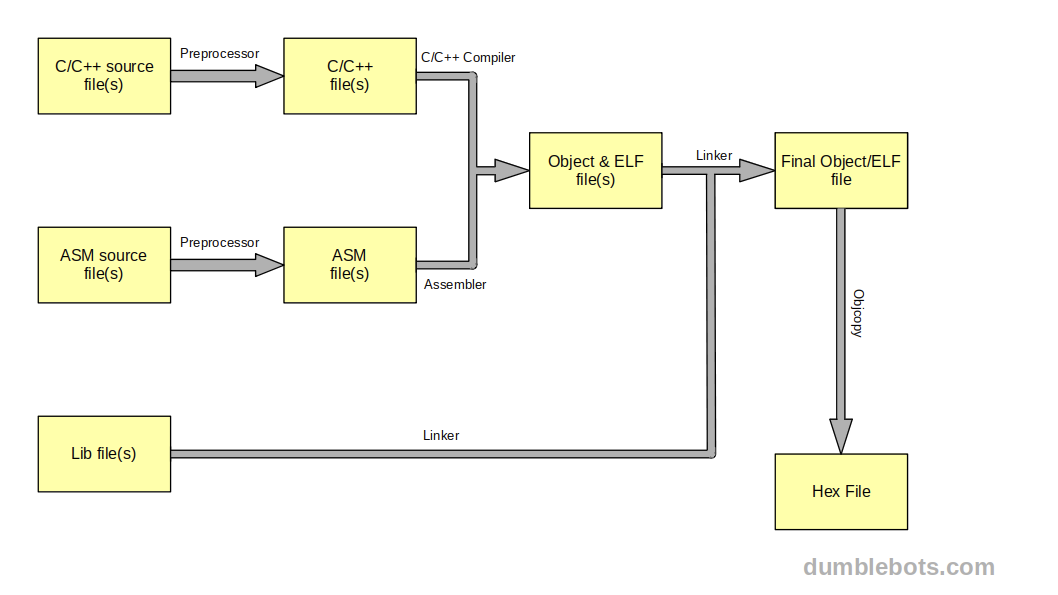
Build process for the Assembly language
Shown below is a diagram to illustrate the build process for C/C++ and Assembly files on AVR microcontrollers. The two are usually shown together because they share a lot of steps and tools, consequently, it helps to understand them better.
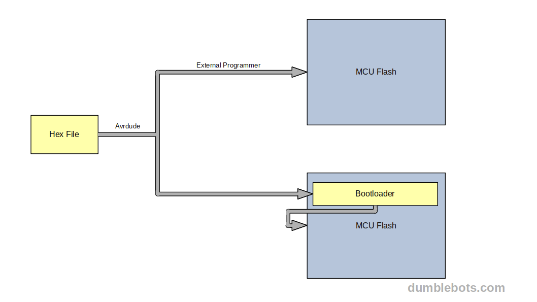
The program will be written to the microcontroller's flash using a tool called Avrdude. Along with Avrdude, we will also require either an external programmer or a bootloader. As mentioned before, the programmer here does not refer to the human writing the code, but to the external device which writes the program to the flash on a microcontroller. We will talk about this more in the coming sections.
Flash process for the Assembly language
Shown below is a diagram to illustrate the process for uploading programs to the flash on an AVR microcontroller.
Setting up the AVR tool-chain
Windows - avr-gcc
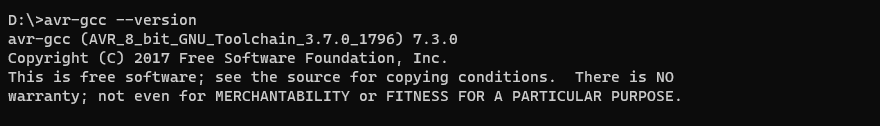
We will first set up avr-gcc. If on Windows, go to the official Microchip website where the tool-chain for 8-bit AVR devices isavailable. Scroll to the Downloads section and click the link next to AVR 8-BIT Toolchain (Windows) to start the download. As of writing this blog, the latest version is 3.7.0.
Extract the downloaded zip file to any convenient location and navigate to the bin directory within to see all the executable command line tools. These tools can only be invoked from within this directory unless the bin directory is added to the system's path variable.
You can test your installation by running the following command, which prints the version information of the compiler.
Windows - avrdude
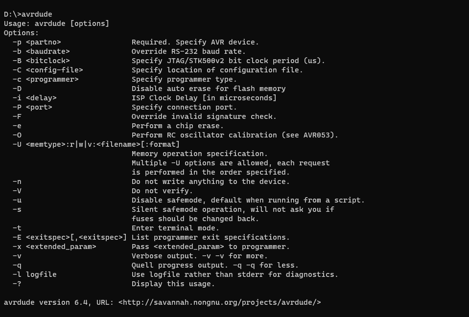
We will now set up Avrdude. On Windows, go to the releases page of Avrdude. Scroll down to the latest version of Avrdude for mingw32 and click on it to start the download. As of writing this blog, the latest version is 6.4.
Create a directory named avrdude-mingw32 in any convenient location. Navigate to the downloaded zip file and extract its contents into this directory. It should have the avrdude.exeexecutable along with some configuration (.conf) files. Once again, to be able to invoke this from outside this directory, it must be added to the system's path variable.
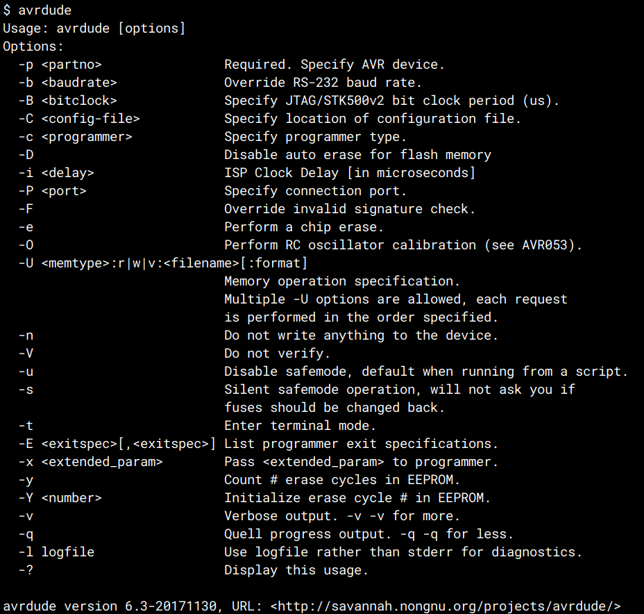
The installation can be tested by running the following command, which prints the usage instructions of Avrdude.
Linux (Ubuntu) - avr-gcc
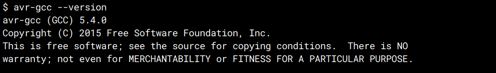
We will first set up avr-gcc. On Linux, you can simply use your preferred package manager to install the toolchain and add it to the path automatically. For example, you can use the apt package manager on Ubuntu, as shown below.
The exact name of the package might differ from one platform to another. Make sure to give it permission to install all the dependencies as well. You can test your installation by running the following command, which prints the version information of the compiler.
Linux (Ubuntu) - avrdude
We will now set up Avrdude. Once again, you can simply use your preferred package manager to install it and have it added to the path automatically. For example, you can use the apt package manager on Ubuntu, as shown below.
The installation can be tested by running the following command, which prints the usage instructions of Avrdude.
Choosing between a programmer and bootloader
If you are familiar with programmers and bootloaders and/or have your programmer already set up and prepared, then you can skip to the next section.
While reading this blog, you might have come across the wordsprogrammer and bootloader a couple of times. They are both tools used to transfer a program to the flash memory of the microcontroller.
Since you cannot directly connect from your USB to the flash on the microcontroller, you must use a special device called an External Programmer. The External Programmer is capable of connecting to your PC on one end (usually through a USB port) and the microcontroller's flash on the other end.
Now, a piece of software running on your PC, like Avrdude (also called a programmer) can transfer a hex file to the External Programmer, which can write it to the flash. You could say that the software and hardware are jointly called a programmer as well.
For example, shown below are an Arduino UNO and ATmega328P connected to an STK500, a popular programmer. Since programmers come in many shapes and sizes, only the connections have been shown.
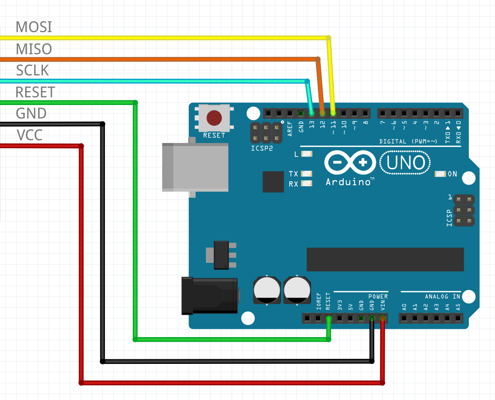
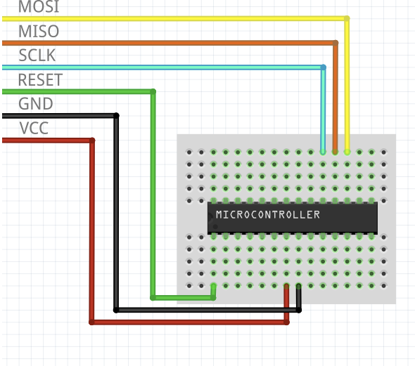
From the above diagrams, it can be seen that the External Programmer connects to regular pins on the microcontroller. When the reset pin of the microcontroller is held at a high state, the microcontroller functions normally i.e. the program currently on the flash is executed and the pins behave as per the program. But when the reset pin is held at a low state, the chip is put into flash mode, i.e. normal program execution is halted. This is when the chip is ready to be programmed/flashed, for which the programmer uses the pins shown above.
While this is happening, the microcontroller does not have to be removed from the circuit it is in. Therefore, external programmers are also sometimes referred to as ICSP/ISP, where ICSP stands for In Circuit Serial Programming while ISP stands for In-circuit Serial Programming. The names can be a bit confusing sometimes but they all essentially refer to External Programmers. You can even use an Arduino (most boards will work) as an External Programmer, click here to read more.
While working with Arduino boards, you may not have had to deal with programmers at all. This is because they use something called abootloader. A bootloader is a special program that resides in the flash memory before your program if any. Its purpose is to wait for and accept an incoming program to the microcontroller's flash.
When the chip is powered up, the bootloader is the first to run and waits for the program to be sent to it. Different bootloaders expect the program to be sent in different ways. A common way is through the Serial/UART interface on the microcontroller. Incidentally, this is also how the bootloaders on most Arduino Boards work (like the UNO, MEGA, etc.) If the bootloader receives no indication of a new program in time, it resumes the execution of the program currently stored in flash.
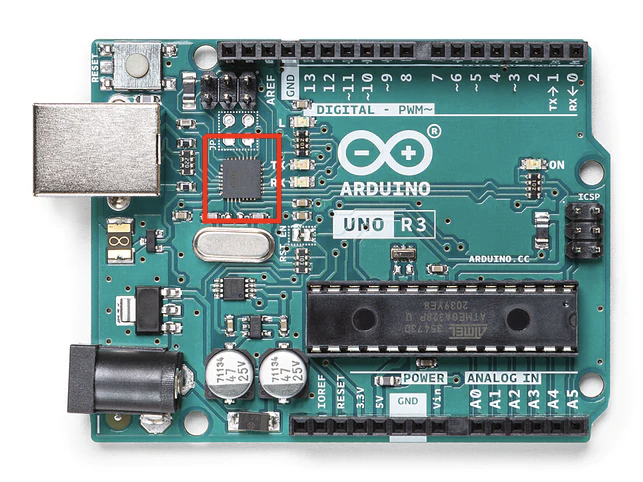
If you choose to use a bootloader, you will still require an external chip capable of emulating UART over USB. For example, a secondary chip is present on the Arduino UNO as shown below which does this. With this emulation and bootloader, Avrdude can now transfer the program from your PC, as if talking to a UART interface.
A bootloader is primarily used to save time during development, as it removes the need to repeatedly connect/disconnect an external programmer from the circuit. The associated cost of a bootloader is that it requires some extra space on your flash. They also make your products vulnerable in production by making it simpler for the user to re-flash the microcontroller.
Both programmers and bootloaders come in many shapes and sizes. You may choose any one and get started for now, as long as it is compatible with Avrdude. To get a complete list of supported targets for Avrdude, run the following command.
The targets include supported bootloaders and programmers. Each target will have its own set of nuances and flags required to use it. For this blog, we will only use the Arduino Serial Bootloader or the STK500/Arduino as ISP programmer.
Building the program
Create a build directory in the same directory as your program. This will contain the final hex file as well as intermediaries.
Let's start by preprocessing the program source file, for which you must run the following command. All commands must be invoked from the source directory.
Let's see what each of the flags does.
The -DF_CPU=16000000UL flag adds an additional preprocessor macro named F_CPU, which evaluates to the frequency of the CPU in hertz. It is not used in Assembly programs but has been added above as a good practice. The UL suffix is added to ensure that the number is interpreted as an unsigned long (unsigned 32-bit) integer.
The -mmcu flag is used to specify the target microcontroller that we are using. If you are using something other than the ATmega328P, then it must be specified here. If you wish to see a complete list of the names of supported microcontrollers, then run the following command.
The above command prints a lot of additional information as well, and you can find the list of names by scrolling to the "Known MCU Names" section.
The -E flag is used to inform avr-gcc to invoke only the preprocessor and nothing else. The -o flag is used to set the name of the output file.
After the command is run, you should see a file called main.s within your build directory, which contains the preprocessed source file. We can now assemble this into an object file, for which you can run the following command.
The -nostdlib flag tells avr-gcc to not link the program with the AVR C language standard libraries. This includes a lot of extra functions which are useful when writing C/C++ but can potentially add significant size/bloat to your program. Since we are not using any of its features, we do not have to link to it.
The -g flag tells avr-gcc to only invoke the assembler and nothing else. The rest of the flags are the same.
After running the command, you should see a file called main.owithin your build directory. Since this is a binary file, it can not be opened in a regular text editor. It contains the entry points for all your functions along with some other metadata. We can now perform the link step to produce the complete program. Run the following command to do so.
As it did was with avr-gcc, the -o flag tells the linker the name of the output file. After running the command, you should see a file called main.elf in your build directory. Sometimes, people prefer to not use the ".elf" extension at all and leave the file extension less. To convert this file into a hex file, run the following command.
The -O flag tells avr-objcopy about the format of the output file. In this case, we are using the Intel hex format, which is compatible with Avrdude and produces small files. After running this command, you should see a file called main.hex in your build directory. We can now run Avrdude to flash this to the microcontroller.
Before we upload the program, it is interesting to check out the size of the final program, along with a section-wise breakdown. Run the following command to do so.
The output of the above command should look as follows.
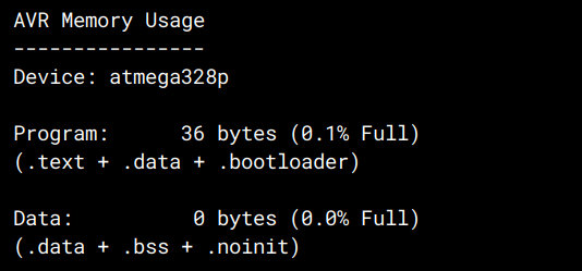
The complete program is only 36 bytes long!
While writing conventional programs, it is not uncommon to see sizes in the order of megabytes or even gigabytes. Sometimes, it is surprising just how small a functioning program can be in the embedded world, especially when using the Assembly Language.
Uploading the program to the microcontroller
First, you must find the serial port to which your Arduino/External Programmer is connected. On Windows, you can do this by going to the device manager and expanding the "Ports (COM & LPT)" section. One of the entries in the list is supposed to be your microcontroller. The ports should have a "COM" prefix followed by the port number (such as COM1, COM2 etc.) If there are multiple entries, simply disconnect and reconnect the Arduino/Programmer. The entry that disappears and re-appears is the correct one.
On Unix based operating systems, run the following command.
This lists all serial ports which are currently in use. To find out exactly which one, run the command once after disconnecting the Arduino/Programmer, and once again after connecting it. The entry which appears solely in the second list is the correct one.
Assuming the port name is COM1, and the programmer is an STK500/Arduino as ISP, run the following command from the source directory.
If you are using the Arduino bootloader instead, run the following command.
Let us see what each of these flags do.
The -v flag tells Avrdude to print detailed (verbose) information. It is not necessary to use, but helps in debugging if something goes wrong.
The -p flag is used to specify the target to program, in this case, we have used the atmega328P target. If you are using something else, specify it here.
The -c flag is used to specify the external programmer/bootloader we want to use.
The -P flag is used to specify the port on which the Arduino/Programmer is connected.
The -b flag is used to specify the baud (bit rate) that we want to use. You can experiment with faster and slower rates, but 19200 is a safe number to use, and fast enough in most cases.
Lastly, the -U flag is used to specify the file we want to use along with the memory-type, operation and file format. It is written as follows.
memtype is the type of memory (eeprom, flash, fuses, extended fuses etc.) we want to use. We specify flash, since we want to write to the flash.
op is the type of operation (read, write or verify) we want to perform. We specify w, since we want to perform the write operation.
filename is the path to the file we want to use.
Finally, format is the type of hex file we are using. We specify i, since we want to use the Intel Hex format.
To see the complete list of options you can use with Avrdude, visit the manual.
After uploading the program, you can connect an LED to the appropriate microcontroller pin (pin 13 on Arduino boards, physical pin 19 on the ATmega328P) and see it blink. And that's it!
You just wrote, built and ran a complete program in the Assembly language for your AVR microcontroller.
Conclusion
A good understanding of the Assembly Language and its execution on the microcontroller, helps to see the finer details of how your code gets operated by the CPU. Additionally, doing it without an IDE exposes the tools and steps involved. This has significant carry over into more conventional, higher level development as well, and enables leaner and more optimized programming. It can also act as a handy tool when compiler optimization occasionally produces undefined behavior.
To see more examples of the Assembly Language for AVR microcontrollers, you can go to this repository. If you have any interesting examples to share, feel free to contribute!
I hope you found this blog interesting and learned something new. If you have any thoughts or queries, drop them in the comments down below, I'd love to know them! Good Luck!