How to make a Paint app example on a 3.5 inch TFT LCD Display and Arduino (Part 5 of 6)
By Aditya
/
July 27, 2024
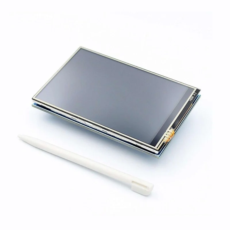
This blog shows how to use a 3.5 inch TFT LCD touchscreen with an Arduino to create a Paint app, which includes a canvas to draw on, a color selector, and a stroke-size selector. It is the fifth out of six parts showing how to use a 3.5" TFT LCD Shield (driven by an ILI9486 driver) with an Arduino UNO R3/R4/Mega for beginners. The blog contains two sections. The first section explains the architecture of the paint app, while the second section shows the circuit and code for the example. This project is a fun way to combine and verify the learning from the previous parts of the series. Creating rich GUIs in embedded systems could be a powerful addition to your toolbox, and this blog acts as a stepping stone for the same.
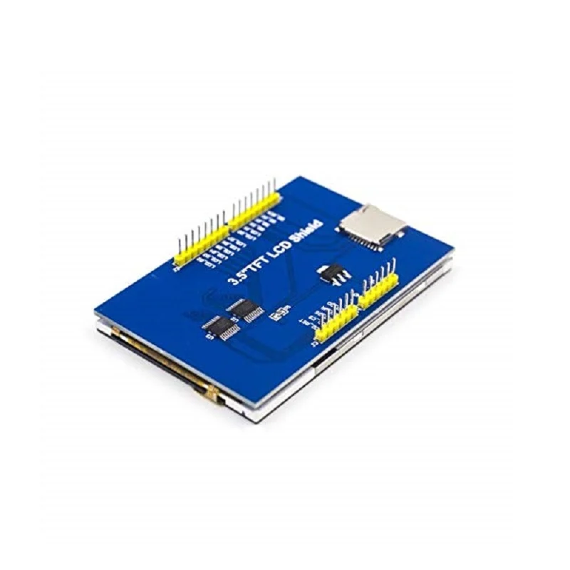
The ILI9486 TFT LCD shield has a thin film transistor (TFT) liquid crystal display (LCD) with a generous resolution of 480x320 pixels & 16-bit color depth (65,536 unique colors), a builtin touchscreen, and abuiltin SD Card slot. It is sold under different names, a popular one being ILI9486 MCUFRIEND TFT LCD Shield, and its form factor and low-cost make it a very attractive option to add rich display capabilities to your Arduino projects.
This is a comprehensive series of six blogs about interfacing a 3.5" TFT LCD Shield with an Arduino Board (including the newer UNO R4 Minima/WiFi). For an introduction to the display and the libraries, refer to the first part of this series. To see how to calibrate and use the touch screen, refer to the second part of this series. To see how to use text files with the library, refer to the third part of this series. To see how to store/display image files with the SD Card, refer to thefourth part of this series. The sixth part of this series shows how to use the TFT LCD Shield to create the popular Tic-Tac-Toe game.
All the examples given in this blog (and series) have been tested on the Arduino UNO R3, Arduino Mega, Arduino UNO R4 Minima and Arduino UNO R4 Maxima. This blog uses the Adafruit GFX, Adafruit Touchscreen and MCUFRIEND libraries for performing various tasks with the displays, and the SPI library and SD Card Library to communicate with the SD Card.
Let's get started!
Briefly recapping the previous parts
The first part of this series went over the hardware components of the ILI9486 TFT LCD Shield, and showed the libraries required to operate it (along with their installation). It also covered the software architecture used to drive the display and ran some builtin examples as well as our own programs to verify its working.
The second part picked up from here and comprehensively talked about and demonstrated the calibration of the ILI9486 TFT LCD's touchscreen (along with a program and video).
The third part moved the focus to the SD Card slot on the TFT LCD Shield and showed how to load/store text files, using both builtin examples and our own examples focusing on practical use cases.
The fourth part explained the bitmap format and showed a program to store and display image files from the SD Card to the TFT LCD Shield.
This blog moves on from the SD Card and shows how to use the learning from the previous blogs to build a Paint app.
Architecture of Paint app with ILI9486 TFT LCD Shield
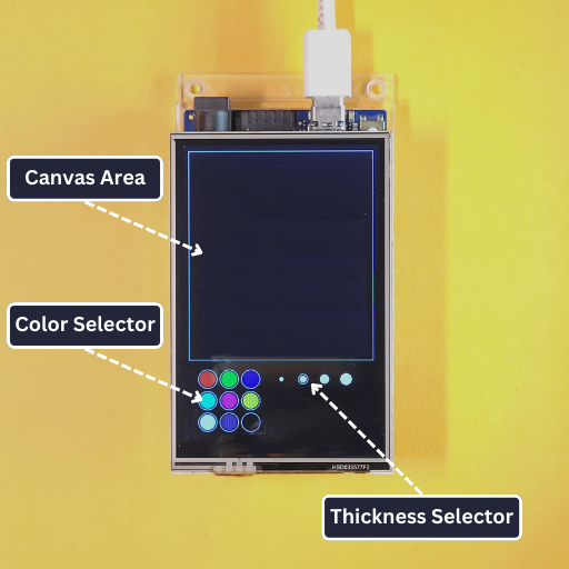
Before seeing the code, let's go over the architecture of the program. This will make it easier to understand the code later. As mentioned before, the application includes 3 widgets -
| Widget | Purpose |
|---|---|
| Canvas | Area to draw on. Starts off as an empty black rectangle with a thin white border. |
| Color Selector | Used to set pen color. Appears as a grid of 3x3 circles with white outlines. Each circle is drawn as a well from a color palette. Tapping a well changes the pen color to the well’s color. |
| Stroke-size Selector | Used to set pen size. Appears as 4 circles with increasing radii, with their centers placed on a horizontal line. The selected size has a white outline around it. The color of the circles is the current pen color, i.e. it must be changed each time the color selector is used. |
As explained in the first part, a widget is a re-usable element in a user-interface with its own appearance and behavior. Examples of widgets are buttons, sliders, text-boxes etc. In the paint application, the canvas, color selector and stroke-size selector are the three widgets that are used.
Each of the three widgets will have a draw and update function. Generically speaking, the draw function is responsible for drawing the widget on the display given its position (and other information that the widget may require). The update function is responsible for receiving events and using them to change the state of the widget. In our case, the only event is a press, i.e. touching the screen. Therefore, the update function must receive the coordinates of the press (when one becomes available) and use this to alter some information about the widget, or even the entire application (such as the selected color, size of the pen etc.)
The flowchart shown below summarizes the execution of a program that follows these rules -
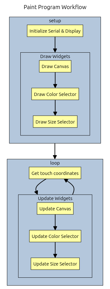
This programming pattern is not unique to the paint app, but used by other GUI applications as well. All the widgets are initialized/created once at the start of the program and drawn.
After this, a mainloop is executed repeatedly, where the events are read and passed to the widgets to act on.
The widget whose bounding box an event occurred on may execute some action based on its current state and type of event. If it contains other widgets within itself, then the event may recursively get passed down to them as well.
We will implement a simple version of this pattern.
Code for Paint app with ILI9486 TFT LCD Shield
This section shows the code for an implementation of the flowchart shown earlier. A video demonstrating the final result is shown below -
The circuit for the project is quite simple as well, involving only the ILI9486 LCD Shield and an Arduino. Create a new project and create the constants.h file. Add the following code in it -
The procedure to create the file, as well as its explanation was given in the second part of this series. In brief, it contains constants that are used throughout the program, and are kept separate from the main file for the sake of readability. The constants are divided into three categories - those used to operate the display, the touchscreen, and application-specific values.
To create the file, click on the downward arrow on the top-right corner of the Arduino IDE
Moving onto the main file, add the following code in it -
The above code implements the flowchart shown earlier. Let us look at it more closely.
The complete code can be found here on Github.
Library inclusion
These lines include the libraries necessary to drive the display, touchscreen as well as the constants.h file. The process to install and use these libraries was shown in the first and second parts of this series.
Global variables
These lines include the creation of the tft and ts objects, which are used to drive the display and touchscreen respectively on the ILI9486 LCD Shield. The lines also include the declaration of the pen_color and thickness_id variables, which store the color of the pen and the index of the pen thickness respectively. We will see their usage shortly.
The color of then pen is stored as a 16-bit number in 5-6-5 format, which was explained in the first part of this series. it starts of as WHITE, whose value is declared in the constants.h file.
Setup function
The setup function initializes the Serial and tft objects and fills the display black to clear it. It then draws the 3 widgets, i.e. the canvas, color selector and size selector using the draw_canvas, draw_color_selector and draw_size_selector functions respectively. We will see the definitions of these functions shortly.
Loop function
The loop function starts by waiting for touch input using the get_touch_coors function. The function returns once an input becomes available after storing the location in the variables x and y.
The coordinates are then passed to the widgets using the update_canvas, update_color_selection and update_size_selectionfunctions. We will see the definitions of these functions shortly.
Note the 5 millisecond delay at the end of the function, which is added to prevent unnecessary updates to the display. As an exercise, you can try changing this value to see how the program reacts after finishing this blog.
Helper functions
These lines include the definition of some helper functions that are used in the rest of the program. The in_range function accepts three arguments and checks if the first argument (called value) lies between the next two (called lo and hi). The distance function calculates the Euclidean distance between two points (x0, y0) and (x1, y1).
Touch management functions
The above lines include helper functions to drive the touchscreen. The valid_touch function returns true if a touch is occurring. The get_touch function reads the touch coordinates and stores them in the variables passed to it as arguments. The convert function converts the coordinates from touchscreen coordinates to pixel values. Finally, the to_display_mode function resets the pins shared by the display and touchscreen back to outputs after the touchscreen is used.
The detailed explanations for these functions was given in the second part of this series. The functions require the touchscreen to be calibrated, which was also explained in the second part of this series.
Widget drawing functions
These lines include the functions to draw the 3 widgets. Thedraw_canvas function is the simplest and involves drawing a single empty rectangle, which represents the edges of the canvas. The position and size of the canvas are given by the constants CANVAS_X,CANVAS_Y, CANVAS_W and CANVAS_H, which are declared in the constants.h file.
The draw_color_selector function comes next, and draws the 9 color wells using a loop. In each iteration of the loop, the location of the current well is calculated (in variables x and y) and its color is fetched (in variable c). A circle is then drawn centered at this location and filled with this color. A second larger circle is drawn outside as an outline, which improves the appearance of the widget.
The relative location of each well is given in the PAINT_COORS array, while the absolute location of the color selector widget is given in the PAINT_OFFSET_X and PAINT_OFFSET_Y variables. To get the absolute location of each well, the relative x and y coordinates of the well are added to the absolute location of the color selector. These 3 constants are declared in the constants.h file.
Relative indicates that the position is given as an offset from a point other than the top-left of the screen, while absolute indicates that the position is given as an offset from the top-left of the screen. In this case, the position of the spots was given as an offset from the top-left corner of the color selector, while the position of the color selector was given as an offset from the top-left corner of the screen.
The draw_size_selector function comes last, and is similar to the draw_color_selector function. It draws the 4 size options using a loop. In each iteration of the loop, the position and size of the current spot are fetched from the THICKNESS_OPTION_COORS and THICKNESS_OPTIONS arrays and used to draw a filled circle. Unlike the color selector, the THICKNESS_OPTION_COORS stores the absolute locations of the spots.
The current pen color is indicated by the color of the thickness selector, while the current pen size is indicated by an outline around the selected thickness.
Widget update functions
These lines include the functions to update the 3 widgets based on touch inputs. Each function accepts two arguments, i.e. the x and y coordinates of the touch point.
As before, the update_canvas function is the simplest of the three. It first checks if the touch point lies inside the bounding box of the canvas, If this condition is met, then a filled circle is drawn centered at the touch point, whose size is given by t and color given by pen_color. If the stylus is dragged across the display and this functions is called often enough, then the spots are drawn close enough to appear as a line, i.e. produce the effect of a marker being dragged across paper.
The condition for intersection is checked using the in_rangefunction, by individually checking the following conditions -
- If the left edge of the stroke
(x - t)lies at least 2 pixels to the right of the left edge of the canvas. - If the right edge of the stroke
(x + t)lies at least 2 pixels to the left of the right edge of the canvas. - If the top edge of the stroke
(y - t)lies at least 2 pixels below the top edge of the canvas. - If the bottom edge of the stroke
(y + t)lies at least 2 pixels above the bottom edge of the canvas.
The update_color_selection function comes next. It iterates over the color spots and checks if the touch point lies on any one of them. If this condition is met, then the value of pen_color is updated, and the size selector is re-drawn (using the new color).
Because the color spots are circles, the condition for intersection is different from the canvas (which was a rectangle). The condition for intersection is checked by calculating the Euclidean distance between the touch point and center of the paint spot (using thedistance function), and checking if this is not more than the radius of the paint spot.
The update_size_selection function last, and is similar to the update_color_selection function. It iterates over the size spots and checks if the touch point lies on any of them. If this condition is met, then the value of thickness_id is updated, and the size selector is re-drawn (with the outline around the newly selected size).
If everything goes well, you should see the following after uploading the program -
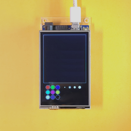
The initial color of the pen should be white while the initial size should be the second one. To change the color options, edit the following lines in the constants.h file -
To see how to create color codes, check out the first part of this series.
Final Thoughts
After finishing this blog, you should have a thorough understanding of how to build complex applications with the display and add rich graphics capabilities to your projects. For a version of the Paint app with WiFi connectivity (allowing saving and loading of your drawings), see this on Arduino Project Hub.
Feel free to leave your thoughts and suggestions in the comments down below. The next part of this series shows how to use the TFT LCD touchscreen with the Arduino to build the popular Tic-Tac-Toe game.