Get started with Mbed OS on Arduino (Part 2)
By Aditya
/
April 6, 2020
In this two-part tutorial, we will get started with Mbed OS (a powerful and lightweight RTOS from ARM) on recent Arduino boards such as those from the MKR and Nano families. Having Mbed OS integration has many advantages such as first class support for connectivity, security and more. This blog is the second of a two-part series, and shows example programs (including multithreading) running on the Arduino Nano 33 BLE and BLE Sense using Mbed OS. The previous part builds up a simple understanding of an RTOS and shows how to set up the Mbed Core on the Arduino IDE, click here to go to the first part.
Simple blinky example
The Blinky program could be considered the Hello World of Arduino Programming. In this section, we will rewrite the Blinky example for the Arduino using Mbed OS functions and classes. For reference, the regular Blinky is shown below.
Start by creating a new sketch, selecting the "Arduino Nano 33 BLE" under "Tools" > "Boards", and including the mbed.h header file in the program. Additionally, bring all members of the mbed, rtos andstd::chrono_literals namespaces into the current namespace through theusing directive. This is required to be able to use all the Mbed OS functions and classes without having to repeatedly prefix them withmbed::, rtos:: and std::chrono_literals::. The code should look as follows -
Unlike in Arduino which uses functions to control the mode and state of the pins, Mbed OS encapsulates this behavior in classes. The following code can be used to create a global object of the DigitalOut class that controls the state of the pin LED1. I have named the object led, but any valid identifier name can be used. LED1, in this case, refers to pin 13 on the Arduino (which contains the built-in LED). A list of all pin numbers and their corresponding Mbed pin names is given at the end of this blog for your reference. The code should now look as follows -
The above code implicitly sets the mode of pin 13, so the setup function can be left empty. Enter the following code in the loop, which switches on the pin, sleeps for a second, switches it off and waits for a second again. To set the state of the pin, the write method of the DigitalOut class has been used. To add delays within the program, the sleep_for function has been used from the ThisThread namespace. The function puts the current thread to sleep for the specified duration, during which other threads (or the OS) can execute.
Unlike the delay function used in regular Arduino programs, the function accepts the time as a chrono literal rather than an integer. The literal consists of a number with a suffix describing the units. For example, to create a delay of 500 milliseconds, the value 500ms should be used. For the current program, we use the value 1s to cause a delay of 1 second. A list of allowed suffixes for chrono literals are given at the end of this guide for your reference.
The complete code should look as follows -
This concludes the Blinky program. You may verify and upload the program as with a regular Arduino program to see the LED blink.
Multitasking by spawning threads
Now that we have finished blinking an LED, let's see how to spawn two threads to perform multiple tasks concurrently, therefore giving the effect of multi-tasking.
Once again, start by including the mbed.h header file and bringing members of the mbed and rtos namespaces into the current namespace. Also include all members from the std::chrono namespaces. This will be explained in a bit. Additionally, create two threads called t1 and t2 (you may use any valid identifier name, just make sure to substitute it in the remaining code) as shown below -
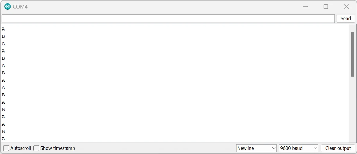
The threads will need functions to execute. Create two functions called func1 and func2. These functions should not return any value or accept any arguments. These functions will print the characters "A" and "B" to the Serial Monitor every 2 and 3 seconds respectively. The functions are also required to never return, so the code within them has been placed within infinite for(;;) loop blocks.
Finally, place the following code in the setup function to being Serial communication and start executing the threads using the provided functions. The loop function can be left empty.
The complete code should look as follows -
This concludes the multi-tasking example. You may verify and upload the program as with a regular Arduino Program and upload the Serial Monitor to see the output.
I hope you found this two-part series interesting and learnt something new. If you have any thoughts or queries, drop them in the comments below. I'd love to know them! Good Luck!
Reference
Allowed suffixes/units for chrono literals -
| Suffix | Units of resulting literal | Examples |
|---|---|---|
h | integral/float-point hours | 1h, 1.5h |
min | integral/float-point minutes | 10min, 20.5min |
s | integral/float-point seconds | 1s, 2.5s |
ms | integral/float-point milliseconds | 500ms, 50.5ms |
us | integral/float-point microseconds | 750us, 1.5us |
ns | integral/float-point nanoseconds | 1ns, 10.5ns |
Note that while all of the above literals are syntactically valid, the sleep_for function only accepts integral hours, minutes, seconds and milliseconds. Providing floating-point versions of these literals, or literals with smaller units causes an error during compilation.
Pin mappings from Arduino to Mbed -
| Arduino pin number | MBed pin designator | Microcontroller pin name |
|---|---|---|
| D0 | P1_3 | Port 1 Pin 3 |
| D1 | P1_10 | Port 1 Pin 10 |
| D2 | P1_11 | Port 1 Pin 11 |
| D3 | P1_12 | Port 1 Pin 12 |
| D4 | P1_15 | Port 1 Pin 15 |
| D5 | P1_13 | Port 1 Pin 13 |
| D6 | P1_14 | Port 1 Pin 14 |
| D7 | P1_23 | Port 1 Pin 23 |
| D8 | P1_21 | Port 1 Pin 21 |
| D9 | P1_27 | Port 1 Pin 27 |
| D10 | P1_2 | Port 1 Pin 2 |
| D11 | P1_1 | Port 1 Pin 1 |
| D12 | P1_8 | Port 1 Pin 8 |
| D13 | P0_13 | Port 0 Pin 13 |
| A0 | P0_4 | Port 0 Pin 4 |
| A1 | P0_5 | Port 0 Pin 5 |
| A2 | P0_30 | Port 0 Pin 30 |
| A3 | P0_29 | Port 0 Pin 29 |
| A4 | P0_31 | Port 0 Pin 31 |
| A5 | P0_2 | Port 0 Pin 2 |
| A6 | P0_28 | Port 0 Pin 28 |
| A7 | P0_3 | Port 0 Pin 3 |
| Power LED | P1_9 | Port 1 Pin 9 |